
 FR
FR 
The opportunity to carry out a structural diagnosis of the Fort of Socoa made it possible to study the mechanical behaviour of an annular vault under seismic loading.
Far from modern engineering structures, this military construction raises fundamental questions.
- What modelling strategy should be used in an engineering context?
- How can the stereotomy and complex shapes of such a structure be approached?
- How should the seismic issue be considered within a regulatory framework sometimes ill-adapted to historic structures?
- What are the expected failure modes, and how do they compare to those of classical masonry structures?
- Which indicators and stability criteria should be retained?
To answer these questions, we propose a comprehensive methodology combining parametric geometric generation and structural analysis using the discrete element method.
This study reveals a unique collapse mechanism, hybrid between that of a dome and that of an arch. Above all, it once again demonstrates the ability of masonry to reach a new equilibrium state despite the presence of cracking, confirming the resilience of stone structures. This study thus offers a pathway for the structural justification of complex masonry works subjected to seismic actions.
Authors: Vincent VENZAL, Julien PERARD, AIA Ingénierie
Keywords: Masonry, Discrete Element Method (DEM), Parametric stereotomy, Frictional cohesive zone model, Seismic vulnerability
INTRODUCTION
As part of a diagnostic and project-management assistance mission entrusted to the engineering firm AIA Ingénierie by the Communauté d’Agglomération Pays Basque, a structural study was conducted on the Fort of Socoa, located in the municipality of Ciboure (FIGURE 1). The objective of this mission was to assess the structural condition of the fort and analyse the seismic vulnerability of the tower, the main structure within the site.
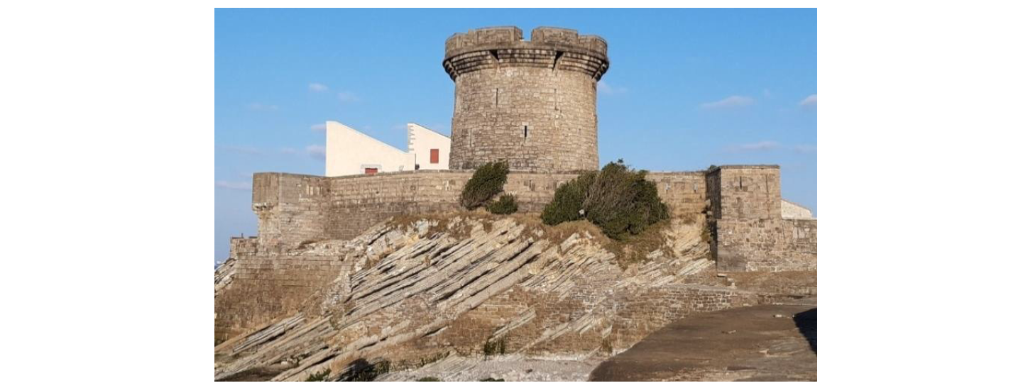
FIGURE 1. Fort de Socoa
The Fort of Socoa was built at the beginning of the 17th century for military purposes. Constructed from local stone, it underwent several modifications, notably by the engineers Vauban and Ferry, and contributed to the protection of the Bay of Saint-Jean-de-Luz until the mid‑19th century. A symbol of France’s maritime defensive heritage, the structure is now listed as a Historical Monument but remains closed to the public due to lack of maintenance and assigned use. The structural diagnosis carried out on the main tower revealed minor façade defects (surface cracking, vegetation…), but the overall structural condition remains good, supporting the hypothesis of oversizing due to its military purpose.
FIGURE 2 details the structural principles of the construction, its main dimensions, and the historical functions of the various levels. The floors of the tower are supported, at the ground-floor upper slab and the third-floor upper slab, by two stone annular vaults. Although relatively common in French architectural heritage, these vault types appear to have been the subject of limited study in scientific literature (Líndez and Rodríguez, 2015). This article focuses on the mechanical behaviour of the two annular vaults, particularly under seismic loading.
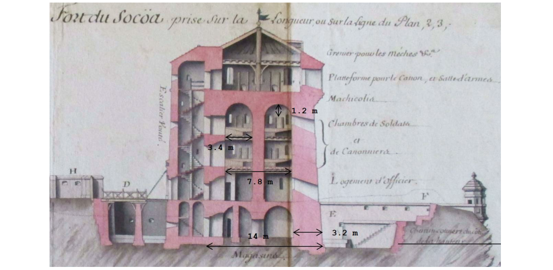
FIGURE 2. Section of the Fort de Socoa tower by the engineer Ferry in 1698
METHODOLOGY
Describing the mechanical behaviour of masonry structures still encounters scientific and technical challenges today, as demonstrated by the diversity of modelling strategies found in the literature (D’Altri et al., 2020; Roca et al., 2010). Unlike modern structures—whose materials and design methods are standardised and well characterised—heritage stone constructions are marked by significant heterogeneity of their masonry components, empirical construction techniques, and curved geometries. Annular vaults, being both masonry and complex in shape, combine all these difficulties.
We therefore first address the geometric and stereotomic description of the structure by detailing a parametric model of the vault. Once the geometry is defined, two complementary structural analyses are carried out.
A first approach based on the work of Heyman (Heyman, 1995) considers the vault as a membrane subjected to its self-weight. The results provide a preliminary understanding of the behaviour of the structure, highlighting tensile zones and offering a comparison point for more advanced numerical analyses.
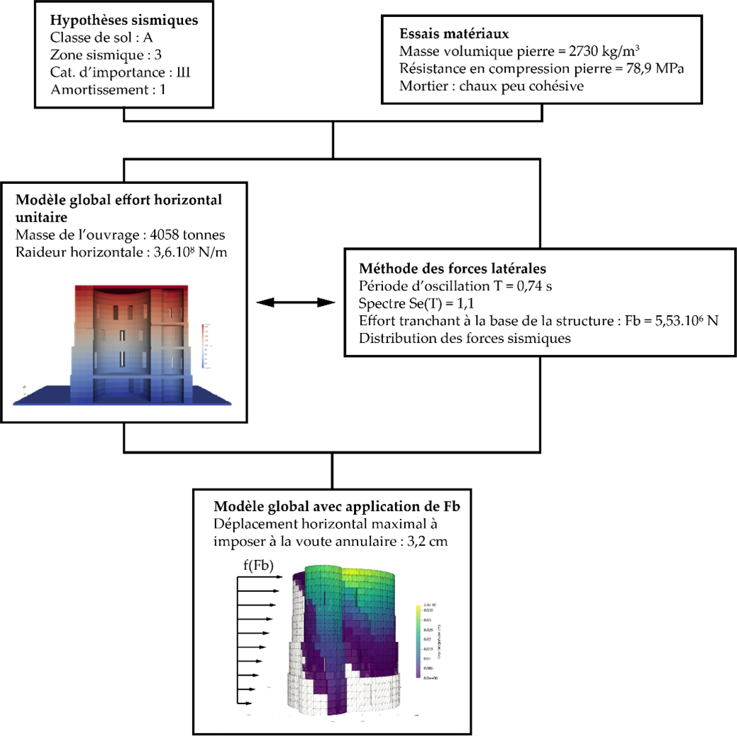
Figure 3. Flowchart illustrating the overall methodology leading to the seismic vulnerability analysis of the annular vault
A second approach, using the LMGC90 discrete element (DE) computing code (Dubois et al., 2011), aims to characterise the structural stability, crack patterns, and stress distribution under seismic loading. The seismic vulnerability of the annular vaults is analysed using a global model of the tower. The tower is subjected to static horizontal loads representative of seismic action, determined using the lateral force method described in Eurocode 8 (NF EN 1998‑1, 2005). This initial step, not presented in this article, quantifies the horizontal displacement of the tower resulting from the seismic load. This displacement is then imposed around the perimeter of the annular vault under study. The overall methodology summarising all steps leading to the structural justification of the annular vault is presented in Figure 3. The preceding analyses and calculations are considered input assumptions.
It should be noted that several studies have analysed the collapse behaviour of masonry structures under seismic forces not through equivalent static displacement but by loading the structure with seismic records (Clementi et al., 2019; Ferrante et al., 2024). Although these methods better represent dynamic phenomena, they are computationally expensive and can be complex to justify within current regulations.
GEOMETRY
The first step consists in defining the geometry of the annular vault in order to reproduce it numerically. This begins with a 3D scan and dimensional surveys of the structure (FIGURE 4). The intrados is then modelled as a surface of revolution generated by rotating an arch around a central axis. The model is created in Rhino‑Grasshopper (McNeel and Associates, 2021) using a parametric approach to best match the existing vault.
The surface of revolution is parameterised by the following equation:
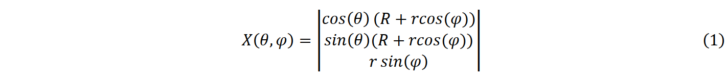
With [θ,φ] ∈ [0,2π] × [0,π] for a complete semicircular arch; r being the radius of the arch and R the distance from the arch centre to the axis of the central pillar (R > r).
The parameters are determined from the drawings and overlaid on the point cloud of the existing structure (FIGURE 4). Xθ and Xφ denote the first partial derivatives of X (Equation 1) generating the tangent plane to the surface. For this specific parameterisation, Xθ and Xφ are everywhere tangent to the parallels and meridians, which correspond to the lines of principal curvature of a surface of revolution.
For the chosen parameterisation, the radii of curvature of the surface are defined by the following equations:

We note the sign inversion of r₁ at the top of the arch, which will influence the analysis of stress sign.
One difficulty in block‑by‑block analysis of masonry structures lies in numerically representing the stereotomy. Given the irregularity of the existing stonework and the complexity involved in identifying each stone, a simplified approach based on theoretical laying principles is proposed. The Encyclopaedia of d’Alembert and Diderot (1751) states for an annular vault:
“cylindrical vaults whose axis is curved in a circular manner: when extended, the bed joints of the voussoirs must pass through the axis, and the joints form portions of conical surfaces. The head joints must be perpendicular to the axis, and bonded together as in any good masonry.”
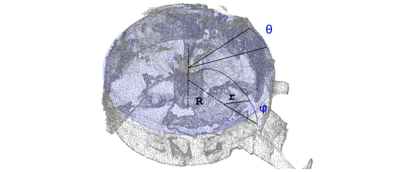
FIGURE 4. Superposition of the surface of revolution onto the intrados point cloud of the annular vault
These stereotomy principles can be observed in many existing vaults (e.g. Palace of Charles V in Granada, Líndez & Rodríguez, 2015). To implement a parametric approach, we rely on Monge’s 18th‑century theory in which the stonework follows the lines of principal curvature of the surface (Sakarovitch, 1998). In our case study, this approach leads to a result consistent with d’Alembert and Diderot’s description. The quality of Monge’s stereotomy is characterised by:
- joint surfaces orthogonal to both intrados and extrados;
- orthogonality between joints of each voussoir;
- joints forming developable surfaces.
The stereotomy algorithm takes as inputs the target block dimensions (length, width, height = 60 × 30 × 30 cm³). This choice is a compromise between existing stone sizes and computational cost. First, the stone beds are defined by dividing the surface along meridians according to block width, then drawing parallels at each segment edge (FIGURE 5.a). Each bed is then subdivided according to the block length (FIGURE 5.b). Finally, block edges are projected along the normal to generate the joint surfaces of thickness t (FIGURE 5.c). Each voussoir is then reconstructed by assembling the joint surfaces with intrados and extrados.
The resulting stereotomy shows some aligned joints, potentially creating structural weaknesses (“coups de sabre”). These arise from the algorithm’s parameterisation, where adjacent beds share block counts with a small common multiple. This issue is removed in the DE model by selecting the quarter‑vault for study.
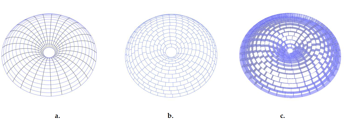
FIGURE 5. a. Generation of stereotomy from principal curvature lines. Blue: parallels tangent to Xθ; black: meridians tangent to Xφ. b. Intrados stereotomy. c. Joint generation.
MEMBRANE-TYPE STRUCTURAL ANALYSIS
We propose here to analyse the mechanical behaviour of the vault based on the work of Heyman (Heyman, 1995), who models masonry as a membrane subjected to its self-weight.
We therefore seek to determine the internal stresses acting on an infinitesimal element of the structure, in the direction of the meridians (denoted σφ) and the parallels (denoted σθ). The equilibrium of forces in the vertical and normal directions is given by Equations 3 and 4 respectively:

With r₀ = R + r·cos(φ); p a constant load equivalent to the surface weight of the vault; t the block height; and r₁ and r₂ (Equation 2) the radii of curvature of the surface.
FIGURE 6.a and FIGURE 6.b show the stress fields resulting from a membrane finite‑element analysis under self‑weight. In the meridian direction, the masonry is everywhere in compression (red), therefore of constant sign. However, in the parallel direction, the masonry is compressed near the central support and subjected to tension (blue) as one moves towards the outer support. This evolution, visible analytically in Equation 4, is directly linked to the geometry of the vault and to the sign change of r₁ along the meridian, while the other terms of the equation remain of constant sign. This stress distribution suggests cracking patterns along the meridians (FIGURE 6.c), reminiscent of those highlighted by Heyman in his analysis of dome behaviour.
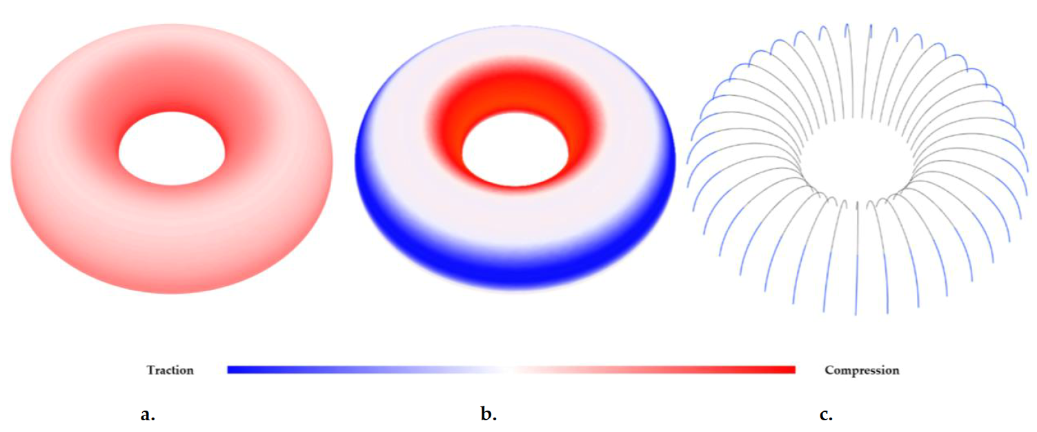
FIGURE 6. a. σφ stresses along meridians, b. σθ stresses along parallels, c. Expected cracking along meridians in tension zones.
DISCRETE ELEMENT METHOD ANALYSIS
The membrane analysis provided an initial understanding of the vault kinematics under self‑weight. We now focus on its seismic vulnerability. For this purpose, a block-by-block model based on the discrete element method (DEM) is used. DEM models are particularly well suited to describing the mechanical behaviour of stone masonry structures because they naturally represent the discontinuous nature of the material by modelling interacting rigid or deformable elements. The mortar–stone interface acts as a mechanical fuse, concentrating damage through a frictional cohesive zone model (FCZM) (Boukham et al., 2024; Venzal et al., 2020).
Material assumptions and constitutive laws
The block-by-block geometric model is exported to the computing code where blocks are modelled as isotropic elastic solids that do not undergo damage. Because of the modelling strategy used, these are extended blocks, i.e., each numerical block includes the actual stone volume plus half the joint thickness around it. This approach, based on Lourenço’s work (Lourenço, 1996), allows the stiffness of the mortar joint to be included within the numerical block. Consequently, the Young’s modulus assigned to each block corresponds to the homogenised masonry modulus proposed by Eurocode 6 (EC6) (NF EN 1996‑1‑1, 2022). The extended block parameters are summarised in Table 1.
The joint behaviour is represented through a frictional cohesive zone model (FCZM). This interface law captures the mixed‑mode interaction between tensile (Mode I) and shear (Mode II) loading, as well as cohesive–frictional coupling under compression–shear loading (Venzal et al., 2020). To supply the necessary parameters for block and interface modelling, data from material surveys were adjusted to match the modelling assumptions. Despite the overall good condition of the mortar, ICP spectrometry tests revealed the presence of a weakly cohesive lime mortar due to the age of the structure. Therefore, following Venzal’s approach (Venzal, 2020), an initial degradation of about 60% relative to laboratory-produced lime mortar was applied to the interface behaviour.
Table 1. Properties of the stones and masonry used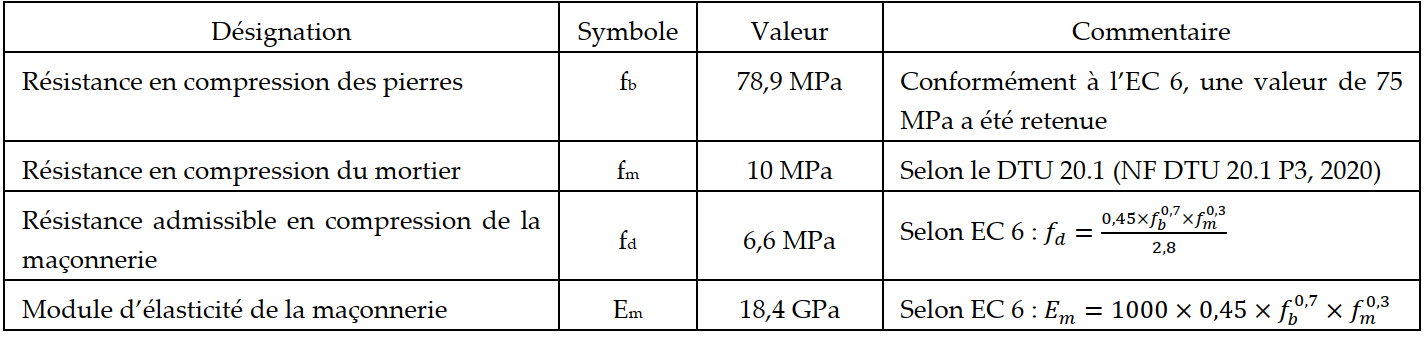
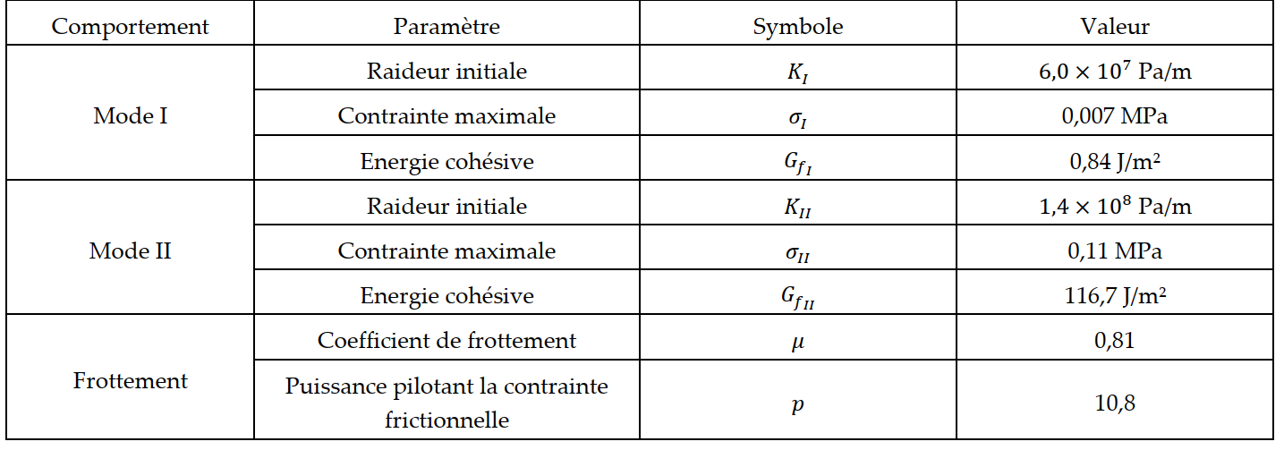
All FCZM parameters depend on a damage variable (d). An initial degradation uniformly reduces the cohesive properties in both tension (Mode I) and shear (Mode II). The degraded cohesive and frictional properties of the FCZM law are detailed in Table 2 (Venzal, 2020).
Table 2. Properties of the degraded FCZM law
Loading and boundary conditions
As previously mentioned, the annular vault rests on the peripheral wall of the main tower and, at its centre, on a stone column. To isolate the mechanical behaviour of the vault, the supports are considered rigid. Because the vault exhibits two planes of symmetry, the numerical model uses a quarter vault. The lateral faces of this quarter are restrained in their normal direction. The boundary conditions applied to the quarter model are shown in Figure 7.
This simplified modelling choice—particularly for symmetry conditions—aims to reduce computation time while remaining on the safe side, which is essential in engineering practice.
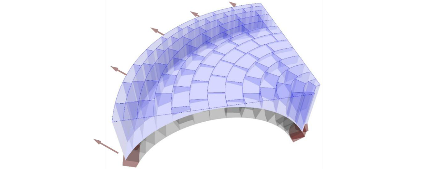
Figure 7. Representation of loads and boundary conditions: vertical load (blue) including backfill, stone pavement and live load; symmetry conditions (grey); rigid supports (red)
Results of the discrete element structural study
To observe the evolution of the structure, the horizontal displacement at the vault perimeter is gradually imposed. Figure 8 shows, at different stages of the calculation, the damage field in the cohesive interfaces. This representation makes it possible to identify the initiation and propagation of cracks along the joints, thereby revealing the collapse kinematics.
At first (Figure 8.a), the initial cracks develop along the meridians in the tensile zones. This confirms the membrane-type analysis presented earlier. As the imposed displacement increases (Figure 8.b), a first crack appears along the parallel at the intrados near the crown. This phenomenon—opening at the crown—is well known in the study of arches.
Finally, Figures 8.c and 8.d show the opening of the haunches at the extrados, also characteristic of arch collapse mechanisms, as well as additional cracking along the meridians. This hybridisation of rupture patterns, combining dome‑like and arch‑like behaviour, is one of the distinctive features of annular vaults.
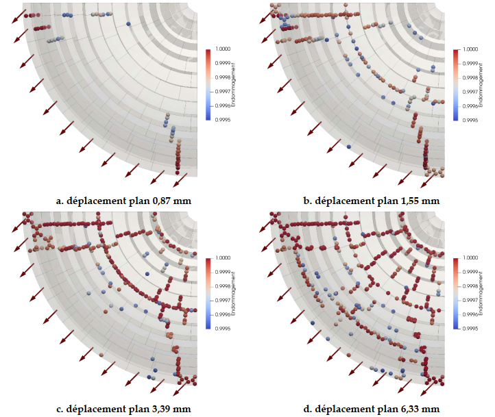
Figure 8. Evolution of cohesive interface damage throughout the numerical analysis
The final state of the vault is shown in Figure 9.a and illustrates the deformed shape, revealing both meridian cracks and parallel cracks.
To confirm the vault’s ability to sustain the applied vertical loads despite the horizontal displacement imposed at its perimeter, the minimum principal stress field (σ₃) within the masonry is analysed (Figure 9.b). The vault is subjected to an average compressive stress of 0.22 MPa and a maximum localised compressive stress of 4.72 MPa at the edges of certain blocks. These values remain well below the compressive strength defined by EC6, i.e. 6.6 MPa (Table 1).
Moreover, despite the presence of significant cracking, the vault reaches a new stable equilibrium state, demonstrating the ability of masonry to form multiple hinges while preserving good load‑bearing capacity.
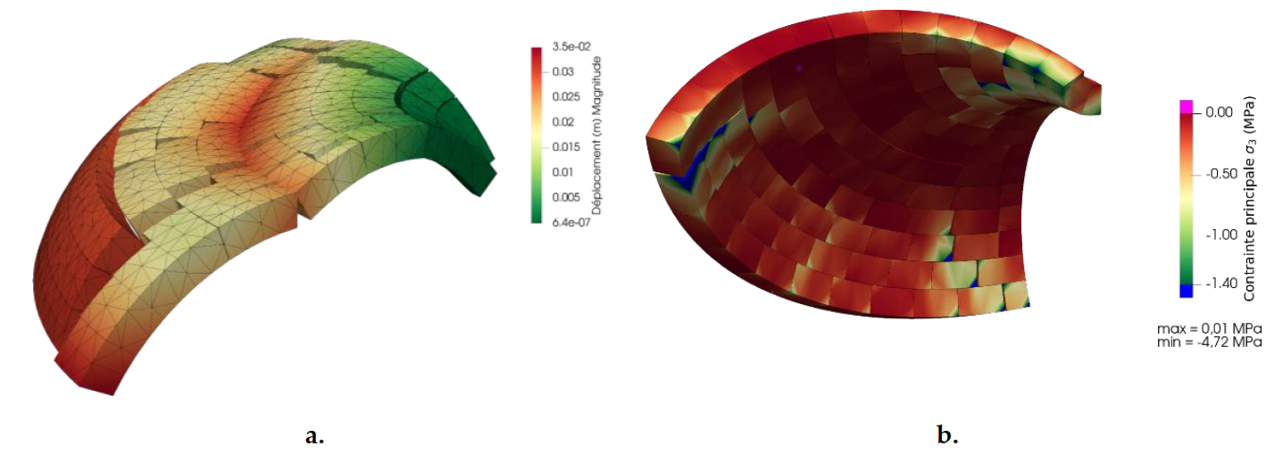
Figure 9. Numerical modelling results: a. Displacement field of the annular vault after full imposed displacement (deformations magnified ×15); b. Minimum principal stress field (σ₃) within the annular vault
CONCLUSION
This article proposes a comprehensive methodology for addressing the structural justification of a masonry structure with complex geometry subjected to seismic loading. To ensure reliability, the methodology combines global structural analysis, material characterisation, regulatory considerations, analytical calculations and advanced numerical modelling. The search for a static displacement reflecting the dynamic action of an earthquake—modelled using the lateral force method from Eurocode 8—maintains a safe, standards‑compliant approach while limiting computational effort.
The article also presents a strategy for the parametric generation of the stereotomy of an annular vault based on a paving algorithm. Although idealised, the resulting geometry respects the stereotomy rules observed in existing annular vaults. In addition, the parametric approach provides modelling flexibility, allowing geometry to be reliably fitted to the scan data while meeting the time constraints of engineering missions.
The block‑by‑block models revealed the singular behaviour of annular vaults, which resembles both that of a dome and that of an arch. After the development of meridian cracks—characteristic of dome behaviour—the joints open at the intrados near the crown, and at the extrados of the haunches, which is typical of arch collapse.
The issue of the seismic vulnerability of historic structures, designed and built using rules sometimes far removed from current regulations, remains an area requiring further study—both for heritage conservation and for the challenges of rehabilitation.
REFERENCES
Boukham, A., Venzal, V., Parent, T., Morel, S., Dubois, F., Solbes, B., 2024. 3D hybrid modeling approach combining the finite and discrete element methods: Validation based on masonry shear wall tests. Int. J. Solids Struct. 289, 112638. https://doi.org/10.1016/j.ijsolstr.2023.112638
Clementi, F., Milani, G., Gazzani, V., Poiani, M., Lenci, S., 2019. Damage assessment by the non-smooth contact dynamics method of the iconic crumbling of the clock tower in Amatrice after the 2016 Central Italy seismic sequence. CEST 2019, Banska Bystrica, p. 420005. https://doi.org/10.1063/1.5114432
d’Alembert, J.L.R., Diderot, D., 1751. Encyclopédie ou Dictionnaire raisonné des sciences, des arts et des métiers. Pergamon Press.
D’Altri, A.M. et al., 2020. Modeling Strategies for the Computational Analysis of Unreinforced Masonry Structures: Review and Classification. Arch. Comput. Methods Eng. 27, 1153–1185. https://doi.org/10.1007/s11831-019-09351-x
Dubois, F., Jean, M., Renouf, M., Mozul, R., Martin, A., Bagneris, M., 2011. Lmgc90, 10e Colloque National en Calcul des Structures.
Ferrante, A., Dubois, F., Morenon, P., 2024. Comparison of Continuous and Discrete Modeling Strategies for the Structural Assessment of a Masonry Vault Under Dynamic Seismic Loading. Int. J. Archit. Herit. 18, 1873–1885. https://doi.org/10.1080/15583058.2024.2377297
Heyman, J., 1995. The Stone Skeleton: Structural Engineering of Masonry Architecture. Cambridge University Press. https://doi.org/10.1017/CBO9781107050310
Líndez, B., Rodríguez, M., 2015. The annular vault of the Palace of Charles V in Granada. Inf. Constr. 67, e125. https://doi.org/10.3989/ic.15.004
Lourenço, P.B., 1996. Computational strategies for masonry structures. Delft University of Technology.
McNeel & Associates, 2021. Grasshopper – algorithmic modeling for Rhino.
NF DTU 20.1 P3, 2020. Masonry works of small units. Part 3: Minimum constructive provisions.
NF EN 1996-1-1, 2022. Eurocode 6 – Design of masonry structures.
NF EN 1998-1, 2005. Eurocode 8 – Design of structures for earthquake resistance.
Roca, P., Cervera, M., Gariup, G., Pela’, L., 2010. Structural Analysis of Masonry Historical Constructions. Arch. Comput. Methods Eng. 17, 299–325. https://doi.org/10.1007/s11831-010-9046-1
Sakarovitch, J., 1998. Épures d’architecture. Springer.
Venzal, V., 2020. Discrete modelling of the mechanical behaviour of stone masonry structures. PhD thesis, University of Bordeaux.
Venzal, V., Morel, S., Parent, T., Dubois, F., 2020. Frictional cohesive zone model for quasi-brittle fracture. Int. J. Solids Struct. 198, 17–30. https://doi.org/10.1016/j.ijsolstr.2020.04.023