
 FR
FR 
Thermo‑mechanical analysis of RC sections: constitutive laws, effects of thermal expansion and thermal gradients, and cases where EC2 requires their consideration.
This article examines the thermo‑mechanical behaviour of reinforced‑concrete members subjected to thermal expansion or thermal gradients, based on the assumptions of Eurocode 2.
It first analyses how the constitutive laws of concrete and steel are modified and how the mechanical diagrams of RC sections (strains, stresses, internal forces) evolve under thermal actions.
The article then reviews the regulatory situations in which thermal effects must be considered, illustrates the physical behaviour that can be observed, and presents the gravity/thermal concomitances that may become governing.
This is the second part of the series “Axial behaviour of flexural reinforced‑concrete elements” (2/4).
Back to the previous article : Axial analysis, concrete shrinkage and thermal expansion in flexural structures – elongation under gravity load (1/4)
Considering thermal effects at the local scale
Modification of concrete and steel constitutive laws
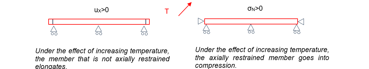
A uniform temperature variation generates stresses in a concrete member when its free expansion is restrained, as illustrated below:
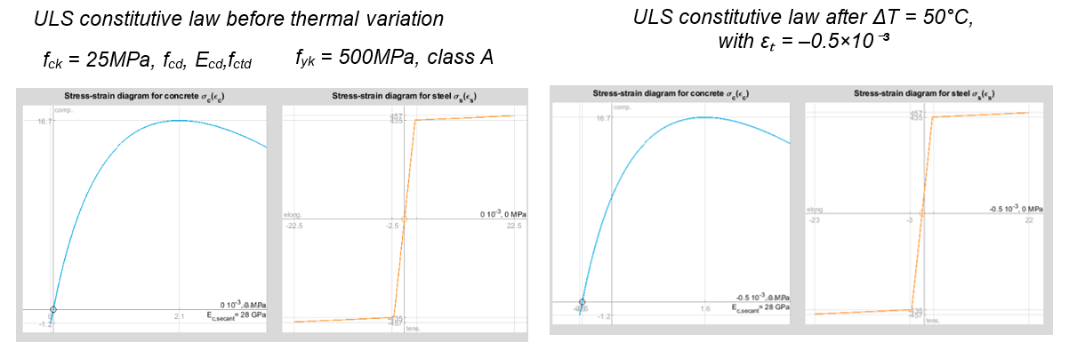
The material constitutive law σ = f(ε) is modified as follows:
σ = f(ε – εT)
with εT = – kT·ΔT and, for concrete and steel: kT = 10‑5 K‑1 (EC2 §3.1.3(4)).
Thus, for a temperature increase of 20°, εT = –2·10‑4:
- If the beam is completely free, σ = 0 even after the temperature increase. Therefore ε = –2·10‑4. A 6 m beam will elongate by ux = ε L = 1.2 mm, regardless of its modulus or section.
- If it is fully restrained, ux=0 so ε=0, which generates a compressive stress σN = –E εT (Hooke’s law f(x) = E x), regardless of its section.
Eurocode allows rounding the linear thermal expansion coefficient kT to a single conventional value for both concrete and steel. This assumption conveniently avoids dealing with self‑stresses between concrete and steel under temperature variations. We will see later that this is not the case for concrete shrinkage.
Some remarks:
- Recall that by convention, ε > 0 corresponds here to shortening and σ > 0 to compression.
- The constitutive curve for concrete behaviour at ULS is not one of the simplified laws (bilinear or parabola‑rectangle), but the most general nonlinear law provided by Eurocode 2, required notably for deformation compatibility studies. In this document we generalise the use of this law for all ULS and SLS studies, with adapted parameters (fcd→fcm, Ecd→Ecm, fctd→fctm…). The tensile capacity of concrete permitted in Eurocode (here fctd at ULS) is included.
- The constitutive curve for steel behaviour at ULS is the bilinear law with inclined yield plateau, also the most precise model provided by Eurocode 2. Likewise, we use this law for both ULS and SLS (replacing fyd by fyk).
- The temperature increase results in a simple horizontal translation “to the left” of the stress‑strain curve. Given the large deformation capacity of steel, especially at ULS in the plastic domain, the expansion effect is barely visible for steel, while it remains very visible in concrete.
- Let us verify the direction of the translation: if the stress is zero (free expansion), the curve indeed gives ε < 0, corresponding to elongation. Conversely, if deformation is prevented (axially restrained piece), the curve gives σ > 0, corresponding to compression.
Modification of mechanical diagrams for reinforced concrete sections
We consider the midspan section of a simply supported beam at ULS, free axially, subjected to a temperature increase of 50°.
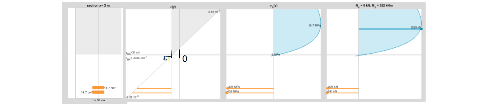
Based on the constitutive laws above, the strain diagram ε(y) is drawn as shown. We assume here that the temperature increase is identical along the entire height (for all y from 0 to h).
The neutral axis depth is defined by the point yNA such that σ(yNA)=0. After thermal variation, this point no longer corresponds to ε(yNA) = 0. This detail matters: above yNA we are in the compressed concrete zone even if ε < 0, and below yNA we are in the tension zone.
Similarly, the elongation of the reinforcement is no longer measured from ε = 0 but from ε = εT, which is why the horizontal bars in the diagram are shown this way. Plotting the line ε(y) = εT is essential in constructing the strain diagram and performing the mechanical study of the RC section.
A temperature gradient through the depth is often approximated as linear. In the example below, the upper surface heated while the underside cooled.
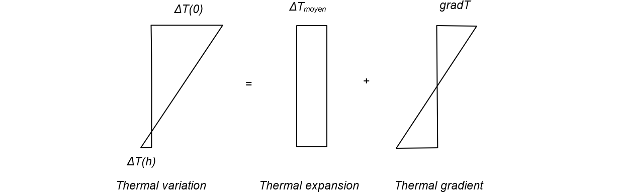
The thermal variation can be decomposed into two components: an average temperature change of the member and a thermal gradient along its height relative to this average.
Let us reconsider the previous example, but now with a 50° increase at the top surface and a 10° decrease at the underside. The section must still balance the same bending moment (522 kNm). The mechanical diagram evolves as follows:
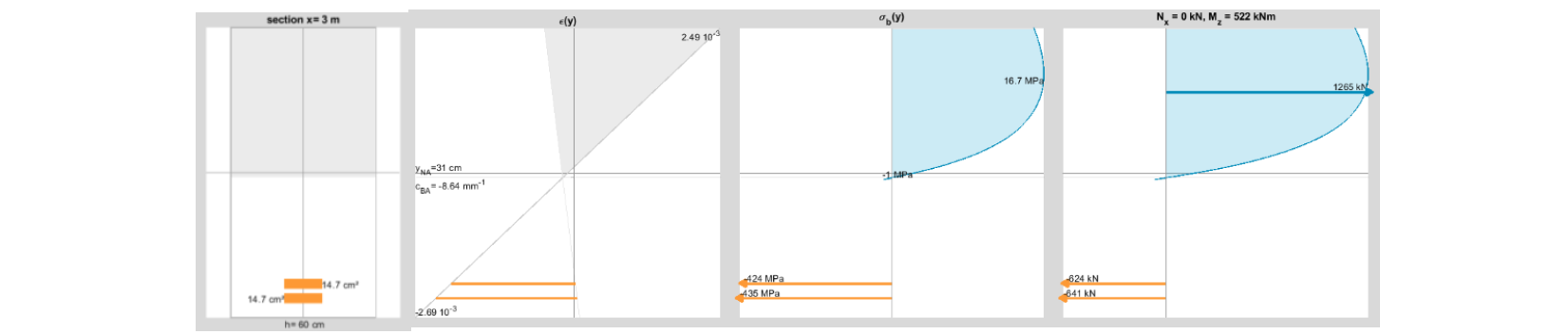
Again, constructing the equilibrium diagrams requires plotting the εT(y) law, which is now no longer a vertical line due to the thermal gradient. Cooling the underside (from +50° to –10°) reduces the curvature and the elongation of the beam — which is physically expected.
When should thermal effects be considered in reinforced concrete structures?
As we have seen, thermal effects can influence curvature and length, and therefore second‑order effects in columns, bending moments in hyperstatic beams, and axial forces in restrained structures.
We will now see that thermal effects must be considered in certain specific verifications, but that their number remains limited to particular configurations.
Eurocode approach to thermal effects
First, in building structures, when block lengths do not exceed the joint spacing djoint defined in EC2 §2.3.3 (3), temperature effects may be neglected in global analysis. Based on the thermal variation (previous diagram), we may therefore isolate the thermal gradient component to study its effect on each member while neglecting the expansion term.
Then, the partial factors applicable to thermal actions (EC0 Table A.1.1): Ψ0 = 0.6, Ψ1 = 0.5, Ψ2 = 0, allow us to deduce that thermal actions are negligible:
- In an accidental load case at ULS‑Acc (unless the thermal action is itself the accidental action)
- In crack‑width verification
- In total deflection verification, both performed at SLS‑QP
For ULS checks, most of the element’s length is governed by plastic steel behaviour (ε from 22.5·10‑3 for class A up to 45·10‑3 for class B). A significant gradient of 50° induces only ±0.25·10‑3 of ε, generally negligible.
This is why Eurocode 2 §2.3.1.2 (2) requires thermal effects to be neglected at ULS, except in specific cases such as:
- Slender columns whose second‑order effects may be influenced by curvature variation induced by a thermal gradient
- Continuous beams with low ductility (highly stressed, e.g., working in pivot B over intermediate supports) where deformation compatibility must be checked after accounting for new curvatures
Effect of the thermal gradient at SLS characteristic
In many cases, the thermal study may therefore be limited to the effect of the thermal gradient at SLS‑Characteristic, with the aim of verifying:
- steel stress limitations
- harmful deflections
- concrete stress limitations (for certain exposure classes)
Indeed, at SLS, materials work in their elastic range, so a variation of ±0.25·10‑3 in ε can be quite significant for these checks.
To ensure a safe and envelope‑based study, it is important to consider concrete tensile strength permitted in Eurocode 2 (fctm or fctm,fl) and the progressive cracking allowed via the ς coefficient (EC2 formula (7.19)). These reduce cracking, making sections less flexible and thus increasing thermal effects.
It is also important to consider creep, so as not to overestimate effects. SLS‑Characteristic corresponds to rare occurrences in the structure’s life; it is reasonable to assume that creep under permanent loads has already ended.
Finally, if creep must be included when assessing thermal effects, the shrinkage effect should also be considered simultaneously, as we will see later.
Design‑driving load cases in the presence of a thermal gradient
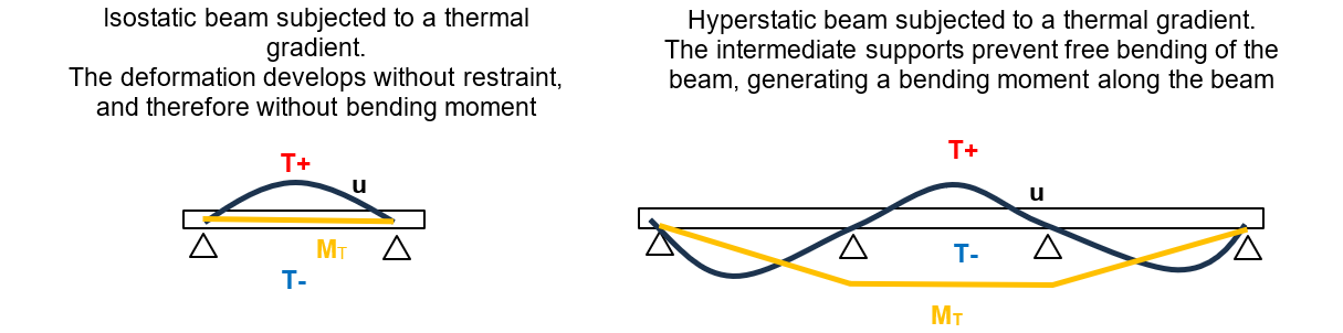
As with the comparison between a freely expanding member and an axially restrained one, the effect of a thermal gradient on a flexural RC beam depends on its degree of hyperstatic redundancy. The example below presents the shape and direction of the deflection u and bending moment M curves for a beam whose upper surface is heated and underside cooled.
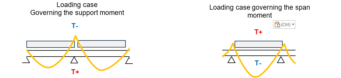
When a thermal gradient is applied to a deformation‑restrained beam, tensile stresses in the cooled‑side steel increase and compressive stresses in the heated‑side concrete increase. Thus, for a reinforced concrete beam subjected simultaneously to service loads and a thermal gradient, the design‑critical cases will be the combinations of loading situations and gradient directions shown below:
In the next article, we address the phenomenon of shrinkage:Axial analysis, concrete shrinkage and thermal expansion in flexural structures - mechanics of shrinkage (3/4)