
 FR
FR 
Analysis of a little‑known axial phenomenon: the elongation of simply‑bent RC beams under gravity loads, a direct consequence of reinforced‑concrete behaviour.
This article introduces the first axial effect observable in flexural reinforced‑concrete elements: the elongation of simply‑bent beams under gravity loads.
This phenomenon—often overlooked despite being non‑negligible—results directly from the fundamental behaviour of reinforced concrete, especially once cracking develops. Understanding it is essential before rigorously addressing the effects of thermal expansion and shrinkage.
It forms the first part of the series “Axial behaviour of flexural reinforced‑concrete elements” (1/4).
A geometric reference for combined bending analysis
The present chapter introduces and explains the calculation approach and the geometric reference framework used throughout the four articles of the series “Axial behaviour of flexural reinforced‑concrete elements” to address the topic.
It is possible to skip directly to the next section on a first reading.
Sequential analysis according to Eurocode 2
By default, according to EC2, the study of a reinforced concrete structure follows a two-step sequence:
- [1] structural analysis using an elastic, linear, uncracked model with mean modulus to determine the axial, shear, and bending forces (N, T, M) along each reinforced concrete element
- [2] reinforced concrete section checks based on the forces calculated in [1]
If we examine in particular the neutral axis depth in a section:
- in the beam theory or finite element model used for [1]: the neutral axis lies at the centroid of the formwork geometry
- in the reinforced concrete calculation model used for [2]: the neutral axis is that of the RC section, cracked if necessary
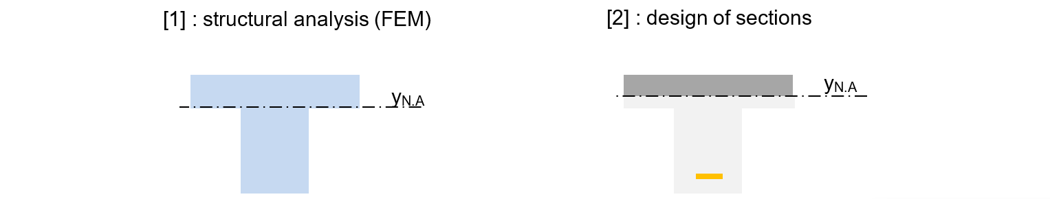
The impact of this difference in neutral axis depth depends on the type of loading on the sections:
- Centric or near-centric compression (columns and walls): the RC section is fully in compression, the neutral axis in [2] roughly coincides with that in [1], and the discrepancy has no meaningful effect (small differences may come from steel distribution).
- Pure bending (beams and slabs): the stress and curvature distribution obtained from [2] is identical regardless of the load application height, since the internal force vector is a “pure moment.” However, the element elongation is inconsistent between [1] and [2].
- Combined bending with cracking or yielding: the same internal force vector will not produce the same stresses in model [1] as in model [2], nor the same curvatures, nor the same elongations.
These differences may become problematic in hyperstatic structures under combined bending, where the N-T-M forces depend on the ability of elements to bend and elongate.
For this study devoted to the axial behaviour of flexural elements, we therefore abandon the default [1]–[2] Eurocode sequence and adopt a single modelling approach in which the input data include not only the formwork geometry but also the reinforcement distribution.
This approach allows determination, within one model, of all structural characteristics: forces, deformations, and stresses, all being mechanically compatible.
A practical geometric convention
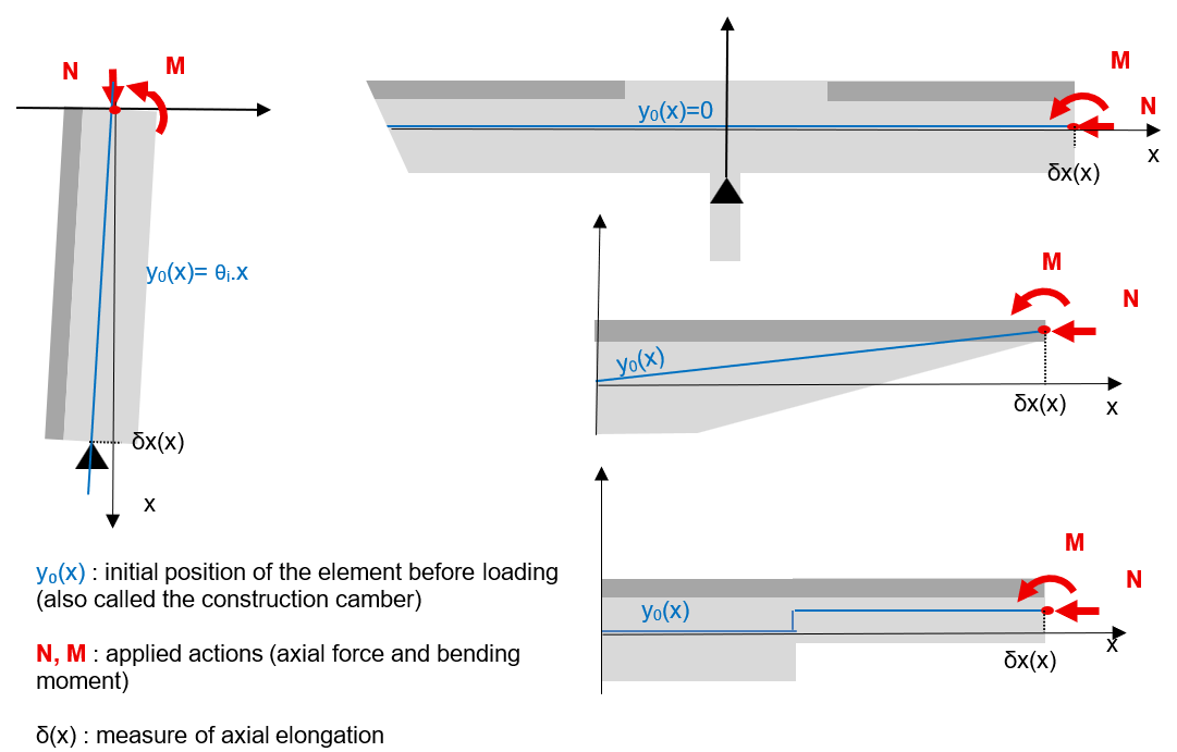
A geometric convention is still necessary for implementing the model. We propose that the reference horizontal axis of the beam always be placed at mid-height of the formwork.
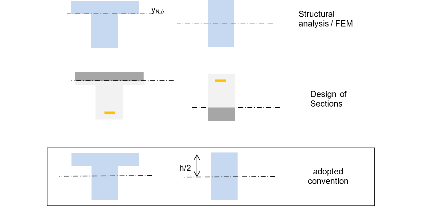
This convention simplifies the parameters for axial supports, loads, construction camber (including geometric imperfections), enables coherent measurement of element elongation (intuitively taken at mid-height), and avoids dependency on variable RC section properties (notably neutral axis depth).
A reinforced concrete beam elongates under gravity load!
The topic of shrinkage and thermal expansion also requires recalling the axial behaviour of elements in pure bending in reinforced concrete.
Reinforced concrete is a material that functions through cracking. As a consequence, any RC beam in pure bending elongates once it cracks—typically under SLS characteristic load and ULS. This elongation is far from negligible and must be considered when studying a member subjected to shrinkage or thermal expansion.
This phenomenon is counterintuitive and cannot be detected in a structural analysis of type [1].
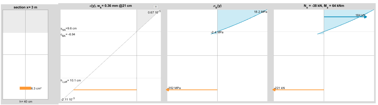
To demonstrate this, we consider a continuous rectangular RC beam of section 30×60 cm, C25/30 with a creep coefficient of 1, reinforced with 6HA20 bottom bars and 3HA14 + 3HA16 top bars, uniformly distributed along the length.
This beam has two 6‑m spans.
Under a transverse load of 70 kN/m, the beam elongates by 1.3 mm over 6 m due to bending. It is indeed the cracked regions that contribute to this elongation, and the bending effects in the spans contribute as much as the bending over the supports.
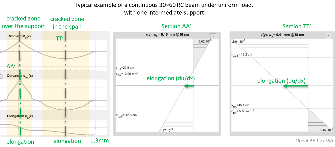
We can add that the elongation of the bottom fibres due to deflection has no significant influence on overall elongation (negligible compared with cracking effects).
To try to eliminate this elongation, one might reduce the beam height h when designing it, so that in the equilibrium of the critical section the neutral axis yNA is closer to mid‑height.
This design strategy, corresponding to a reduced moment µULS = MULS / (b d² fcd) = 0.345, approaches the limit of 0.371, leading to major drawbacks (inefficient tension steel, need for compression reinforcement, or reinforcement densities difficult to implement). It is seldom chosen.
This strategy is mostly ineffective: along the beam, elongation is reduced only near maximum moment sections, and the total length still increases overall.
All reinforced concrete elements in pure bending are therefore affected by elongation.
Slabs, often designed with µULS ≈ 0.10 for deflection reasons, and T-beams, rarely fully mobilizing the slab flange, are among the most sensitive.
Rectangular beams, often designed at 0.25 < µULS < 0.30 at critical sections, are also concerned.
The paradox of the fixed-end RC beam
Let us reconsider the basic case of a statically determinate reinforced concrete beam correctly designed. Its behaviour scheme is as follows:
Let us place this beam in two opposite end conditions:
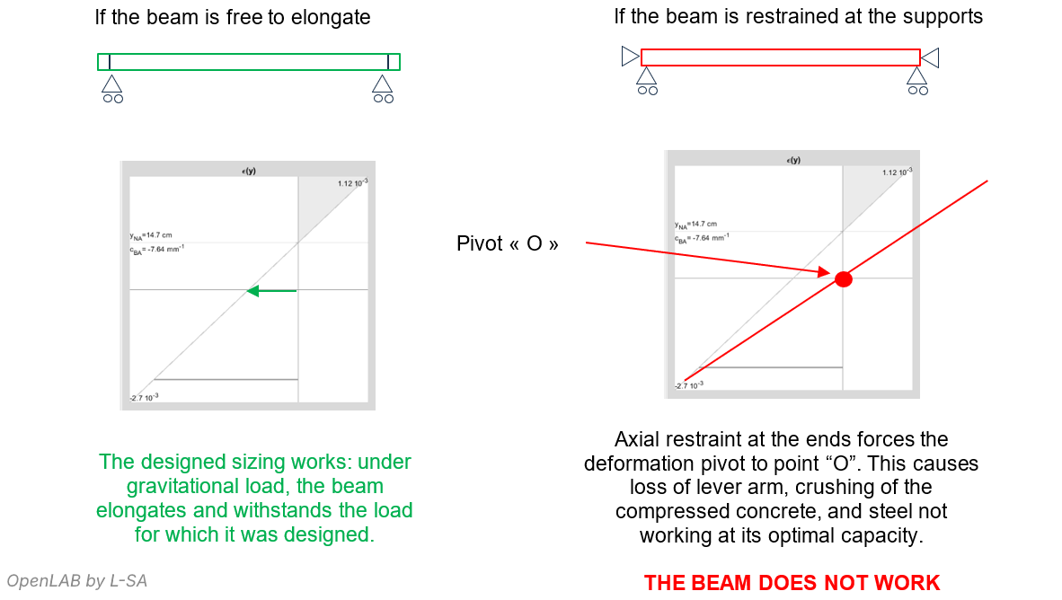
One might think that axially restraining an RC beam provides additional “safety” in design, thanks to confinement. But since axial deformation compatibility is impossible, a reinforced concrete beam cannot function when axially restrained: the steel cannot elongate enough to develop the tensile force required for section equilibrium.
If we study an axially restrained RC beam using the Eurocode 2 scheme, the forces from structural analysis [1] are computed using an elastic model that conveniently places the restraints at the geometric neutral axis. This model bypasses the axial effects inherent to real RC behaviour.
In general, a perfectly fixed RC beam (rotational restraint + axial restraint), or any axially restrained RC element, could be more appropriately designed by keeping the structural analysis [1] but performing the section checks in [2] using neither pivot A nor pivot B, but instead a “pivot O” as defined earlier, to design the steel and verify the concrete.
In the next article, we examine more directly the phenomenon of thermal expansion and thermal gradients:Axial analysis, concrete shrinkage and thermal expansion in flexural structures – thermal expansion and thermal gradient (2/4)