
 FR
FR 
In hyperstatic structures, deformation compatibility dictates the exact distribution of moments — a challenge that the simplified EC2 methods only partially address.
This article explains how a hyperstatic structure possesses, for each load case, a unique exact solution determined by the actual deformability of its sections and supports.
It shows that internal forces depend closely on varying stiffness, reinforcement layout, progressive cracking and plastification, making the EC2 sequential approach sometimes insufficient.
It also explores the conditions for nonlinear analysis, enabling the limitations of the “structural analysis → cross‑section design” framework to be overcome.
This topic constitutes the third part of a series dedicated to the flexural behaviour of reinforced concrete beams (3/4).
Back to the previous article: EC2 Material Laws: Curve Linearisation and Progressive Cracking
Structural hyperstaticity
Generally, in the mechanical analysis of a structure, two situations occur:
- either the structure is isostatic, in which case determining internal forces does not require knowledge of the material behaviour. One can determine support reactions using rigid‑body mechanics, then determine internal forces, for example using the cut‑section method.
- or the structure is hyperstatic, and therefore there are, at first glance, several possible load paths through the structure from loads to supports. To determine the exact load path, it is necessary to consider structural and support deformability, which depends on section geometry and the mechanical behaviour of the materials.
Whether the structure is isostatic or hyperstatic, for a structure whose geometry and material laws are perfectly defined, there exists—at most—one exact unique solution for each load case.
The illustration below shows an example of a second‑order hyperstatic structure: a continuous beam over three spans, carrying a uniform load of 97.5 kN/m. Unlike a simple beam on two supports, it is impossible to determine the four support reactions, bending moment M(x) and shear V(x) without knowing section properties.
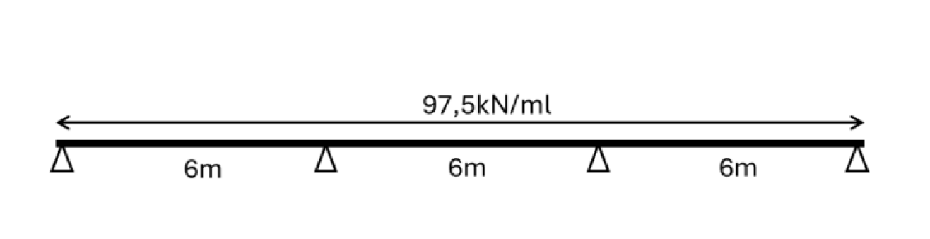
We now specify the example more precisely and assume a linearly elastic beam with variable rectangular cross‑section, ranging from 100×20ht to 100×54ht. Configurations 1 and 2 represent different structural design choices, possibly due to construction methods, geometric constraints or aesthetics.
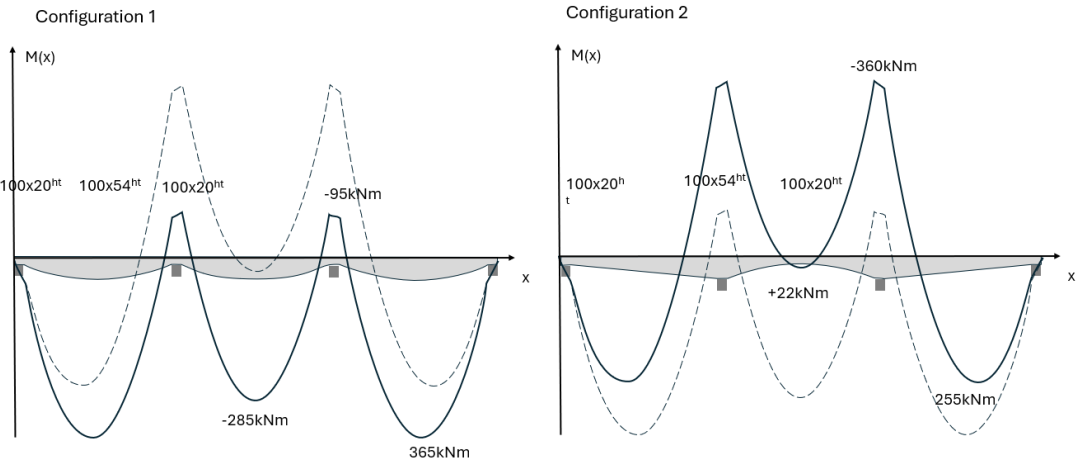
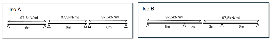
Configuration 1 has greater depth in span, while configuration 2 has greater depth at intermediate supports. A height ratio of 2.7 corresponds to a bending inertia ratio of 20! Each configuration approaches a different limiting isostatic case:
The issue with the EC2 sequential analysis
In the previous example, we considered a simple hyperstatic structure made of linear elastic material with only section height varying. We saw how strongly the internal‑force distribution (M(x)) depends on the structure’s height.
In the domain of reinforced concrete according to EC2, height variations are usually less extreme than in the example. However, the deformability of sections depends on many other parameters:
- material choices: concrete (selected characteristic strength) and steel (strength and class), which may vary within the structure
- section width (and height), possibly affected by stress‑block dispersion
- reinforcement ratio and layout, often continuously variable
- progressive cracking, at both SLS and ULS
- plastification of concrete and steel, especially at ULS
In a hyperstatic concrete structure, we therefore have, in principle, a strong dependence of internal‑force distribution on section properties. This highlights the limits of the general EC2 principle, which proposes to determine internal forces before “designing” the structure and calculating cross‑sections.
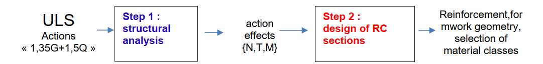
As described in the first article of this series, EC2 §5.4 allows major simplifications of ULS structural analysis to solve this issue and to maintain a functional sequential process without iteration.
Linear elastic analysis thus allows ignoring reinforcement, cracking, plastification and material nonlinearity.
The limited‑redistribution method (§5.5) and plastic analysis (§5.6) are variants of linear elastic analysis in which EC2 introduces simplified plastification mechanisms at limited points to improve ULS structural analysis, while preserving the explicit non‑iterative process between step 1 and step 2.
The following chapter aims to explore the conditions for solving the exact mechanical problem, introducing nonlinear analysis (EC2 §5.7).
Nonlinearity in the behaviour of a reinforced‑concrete section
In addition to continuous variations in geometry along the beam (formwork, reinforcement, material choices), which affect bending stiffness and therefore internal‑force distribution, each cross‑section also experiences large nonlinear stiffness variations depending on bending moment amplitude.
In absolute terms, unless the structural analysis is simplified as previously shown, the very notion of “inertia” is meaningless under EC2 material laws: one cannot relate curvature and moment using a constant EI value.
Thus, in structural analysis, beyond the iteration loop between step 1 and step 2 as sections evolve, we must also include a loop within the structural analysis itself to determine the numerical solution.
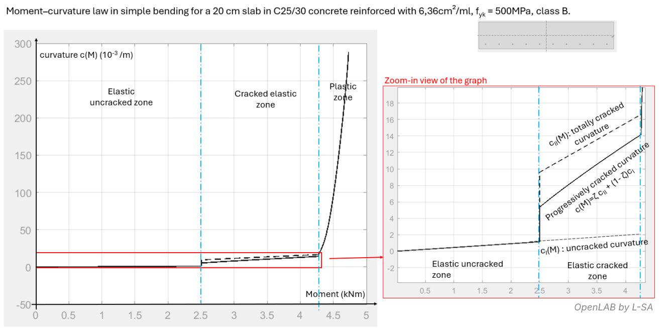
The curves below show the moment–curvature relationship for typical cases of a slab in simple bending:
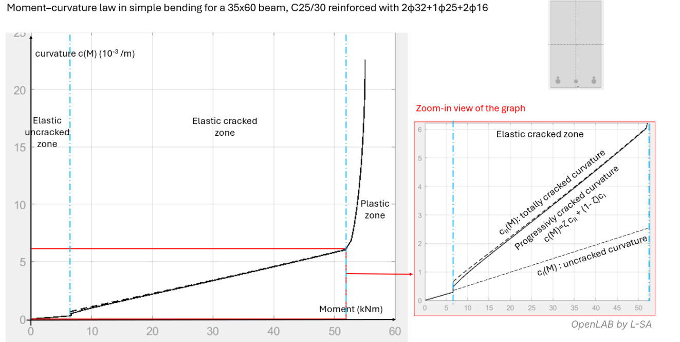
and of a beam in simple bending:
NB: To simplify the exposition, we assume that self‑weight is negligible in action calculations. Strictly speaking, self‑weight creates an indirect dependency between material choice and internal‑force results even in isostatic cases, since self‑weight enters as an action.
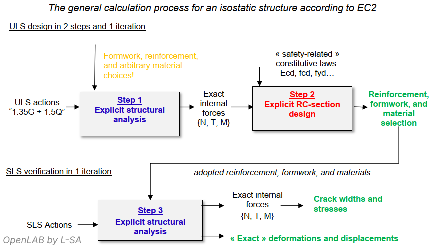
General case of an isostatic reinforced‑concrete system
As mentioned earlier, in an isostatic system, moment and axial‑force distributions do not depend on formwork geometry, reinforcement, or chosen behaviour laws. Therefore, no iterative compatibility checks are required.
The mechanical problem is solved explicitly: first we determine internal forces (N, M, V) without knowing the material laws or section geometry; then we perform section and material design; and finally SLS verifications after updating the structural model.
General case of a hyperstatic reinforced‑concrete system
In contrast, in a hyperstatic beam, it is flexural‑deformation compatibility that determines the exact distribution of moments, cracking, plastification, and ultimately all structural‑analysis results.
To start the calculation, we must make an initial hypothesis about material choices, section geometry and reinforcement layout, since the structural analysis depends on these. Furthermore, structural analysis becomes iterative: internal forces depend on cracking and plastification, which themselves depend on internal forces.
For a given hypothesis on sections, the solution is no longer explicit and requires iterations until the internal‑force distribution stabilises from one step to the next, marking convergence of step 1.
Again, for a fixed beam geometry (concrete and reinforcement), a given load, given material laws and given reinforcement layout, there exists—at most—one distribution of internal forces {M(x), N(x), T(x)} that satisfies compatibility between beam curvature (second derivative of deflection) and sectional equilibrium.
Once this exact solution is obtained, we move on to step 2, i.e. cross‑section design, which remains explicit. As long as step‑2 design modifies resistance classes (fck, fyk), formwork geometry (b, h…) or reinforcement definition (A, A’…), we must restart step 1 with the updated sections.
The calculation of a structure therefore follows a nested double iterative process.
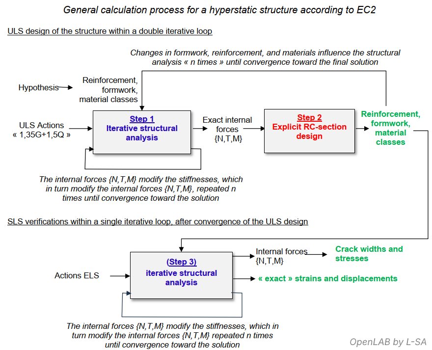
Once ULS design is complete, we proceed with SLS verifications by rerunning the structural analysis using the final sections (formwork, reinforcement and material classes) and applying the various SLS load cases.
Even when geometry and materials no longer evolve, structural analysis for SLS remains iterative, as before, until the unique deformation‑compatible exact solution corresponding to each load case is reached.
In the next article, we go into detail on continuous‑beam analysis according to the simplified EC2 methods: linear analysis, limited‑redistribution analysis, and plastic analysis: Continuous Beams : Plastic Hinges, Redistribution, and the Limits of Elastic Analyses