 FR
FR 
Using the example of a basic parking structure designed with a column–beam system, this article addresses the issues of bracing reinforced concrete buildings, associated best‑practice rules, and the technical constraints and calculations involved in a frame‑type system.
The example highlights horizontal actions that are usually negligible for a car park, but which should be considered when the structure becomes relatively flexible (with sway nodes). It also evaluates second‑order effects that become significant in such a structure.
The numerical solution of the system—made more complex by the absence of horizontal structural elements at the column–pile connection—is provided exactly using the General Integral Method, as an alternative to the use of SOUCHE (1984) design charts.
- General presentation of the topic
- Mechanical modelling of the system
- Horizontal actions considered
- Structural assumptions
General presentation of the topic
We focus on the study of a two‑level open‑air parking structure, associated with office activities and integrated in an environment allowing vehicles direct access from the outside at level 0 and level 1.
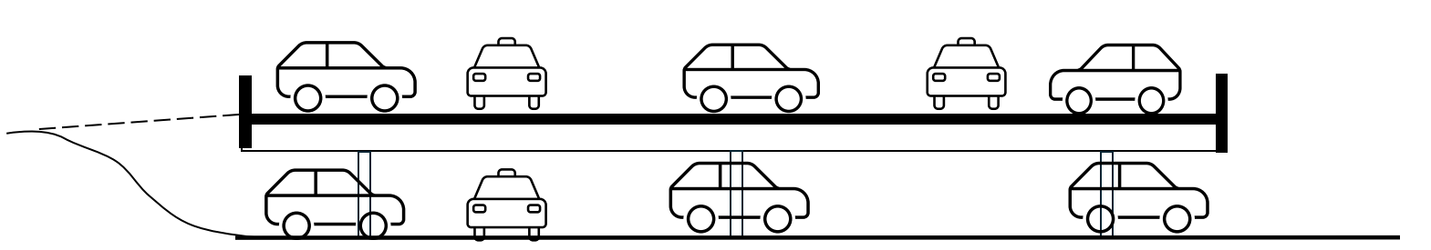
The concrete structure measuring 80m × 25m is divided by an intermediate joint for shrinkage and thermal expansion.
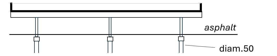
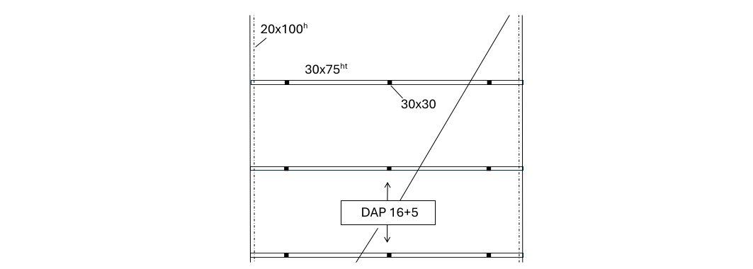
The slab consists of 16+5 prestressed hollow‑core slabs spanning longitudinally on a reinforced concrete column–beam system arranged transversally every 7.80m. Columns are founded on 50cm‑diameter cast‑in‑place screw piles. The level‑0 ground surface is asphalt.
Such a basic structure should pose no difficulty in terms of gravity‑load design. However, several reinforced‑concrete building best‑practice rules are not followed, making the analysis more complex.
Principles of reinforced concrete bracing
First, the structure includes no shear walls.
In reinforced concrete building design, one generally seeks to provide at least three non‑concurrent shear walls per block, working in shear in their plane, to ensure transfer of horizontal actions through the diaphragm formed by the slab.
This arrangement allows shear walls to resist actions in both horizontal directions and vertical‑axis torsion with significant stiffness. The fixity in local column–beam joints and in slab–wall joints becomes negligible compared to the stiffness of the walls.
Since these principles are not applied in the studied structure, bracing necessarily takes place through beam‑to‑column‑to‑pile connections. The resulting braced system has high flexibility, making it particularly sensitive to second‑order effects.
Columns on isolated piles
Additionally, placing columns directly on isolated piles is not recommended, as it may rapidly generate significant stresses in the joints due to execution deviations in layout or inclination relative to nominal values.
Study objectives
The objective of the study is the design of the columns of such a structure under the combined effects of gravity loads, horizontal actions, and execution tolerances.
Under transverse horizontal loading, the floor beams significantly reduce the system’s slenderness because the free column height is noticeably lower and the beams provide substantial partial fixity at column heads.
Therefore, the analysis focuses on longitudinal horizontal actions, which are the most unfavorable case.
Due to the flexibility of the bracing, second‑order effects must be included.
Moreover, since the structure is sensitive to horizontal actions, the dynamic effects of vehicles on the slab—usually negligible in buildings—are considered here.
Mechanical modelling of the system
Configurations defined in Eurocode 2
In the context described above, the column must be classified as a “non‑braced structure” according to Eurocode 2, which can also be interpreted as a “bracing structure.” Indeed, the column head is not horizontally restrained; instead, the column itself must resist an imposed horizontal load.
If the column had:
- a wall‑beam at the top
- a large foundation pad at the bottom, prohibiting both rotation and horizontal translation
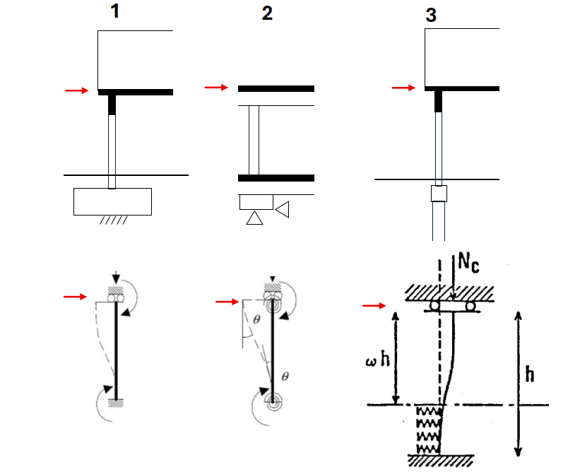
Then, regardless of slenderness, the rotation θ at top and bottom could be considered zero, and model 1—fixed‑fixed with sway—of EC2 Figure 5.7 could be used.
If the column, in the direction of the horizontal action, had:
- a beam at the top
- a ground beam at the base
- a footing blocking any horizontal force by Coulomb friction
Then model 2—partial fixity at both ends—could be adopted, evaluating the I/L ratios between the column and the connected elements (see also this article on determining support stiffnesses).
In reality, in our case, the pile head translates horizontally in addition to rotating. Just like the column head, the pile head is not horizontally restrained. As a result, none of the diagrams of EC2 Figure 5.7 applies.
The column alone cannot be modelled independently: the column base is perfectly fixed to the pile head, forming a continuous system. The combined system {column + pile} behaves like an equivalent deep column embedded in the ground.
The charts of Pierre SOUCHE
This well‑known mechanical system has been studied extensively, notably for micropile design (diameter ≤ 25cm), which is particularly sensitive to second‑order effects in soft soils, or for piles that may be exposed above ground during service or after soil liquefaction.
Numerical studies and design charts were published by Pierre SOUCHE in March–April 1984 in ITBTP Annals No. 423. A 1986 publication on the same topic is also available from CEREMA: SETRA – “Micropiles” (1986).
SOUCHE’s charts address idealized configurations of linear elastic columns of constant inertia, anchored in elastic soil, with pure boundary conditions (perfect fixity or pin).
If our system were fully elastic and the column supported a wall‑beam at the top, model 3 from the charts could be suitable.
The General Integral Method
In our case, we use the General Integral Method to conduct a study including:
- the reinforced‑concrete behaviour of EC2’s General Method, including cracking and material plasticity
- the change in section from column to pile
- execution tolerances, causing either additional mid‑height forces or “construction deflections”
- partial fixity at the column head
- soil plasticity
- compatibility of deformations between column and pile sections
Horizontal actions considered
The aim of this section is not to perform a detailed load calculation, but to highlight specific considerations resulting from the flexibility of the bracing system.
Wind load
Normally, Eurocode 1 recommends the surface‑pressure method (EC1 §5.3 and §7.1(1)) to calculate global wind drag on a building.
However, our structure is not a parallelepiped perfectly attached to the ground, but at least a suspended one, whose exposed area is influenced not only by the geometry of the structure but also by the vehicles parked on level 1.
These vehicles, along with solid guardrails, experience individual drag forces adding to that of the structure and creating roughness elements that may not shelter each other.
Wind analysis—including gable wind—is therefore less straightforward than for a typical rectangular building if underestimation is to be avoided.
Dynamic effects of vehicles
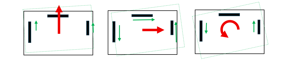
The flexibility of the structure requires particular attention when determining horizontal actions, even if they appear small initially.
Dynamic effects are one example, especially since the functional design and purpose of the parking facility expose it significantly to such actions.
Traffic circulates one‑way, and an expansion joint divides the structure into two blocks. These two features mean that vehicles systematically impose cumulative dynamic effects in both direction and sense: whether braking before the turn, steering during the turn, or accelerating afterward.
The long 80m travel path also encourages significant accelerations and speeds, and the office‑related use implies peaks of usage with many vehicles in motion simultaneously.
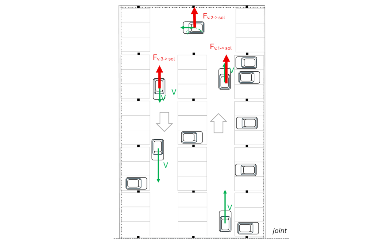
To estimate the quasi‑static horizontal action representing the overall dynamic effect, EC1‑2 proposes mobile imposed‑load models in §4.6(2) for bridges and §5.4(2) for footbridges, mentioning a ratio of 10% of imposed loads.
In the absence of a more detailed evaluation, the following can be used:
Qlk = 10% × 230 daN/m² × 5m × 40m × 2 = 92 kN
This value is comparable in magnitude to the global wind action.
Accidental vehicle impact on a column
EC1‑1‑7, which includes accidental actions such as impacts and explosions, specifies that an accidental load must be considered on structural elements adjacent to vehicle circulation areas, particularly in car parks.
This load, representing vehicle impact, is given in Table 4.1, applied 0.50m above ground, and equal to 50kN in the direction of travel or 25kN perpendicular to it.
Although columns are offset from the circulation lane toward parking spaces, this verification remains relevant for a moving vehicle deviating from the lane.
Execution tolerance effects
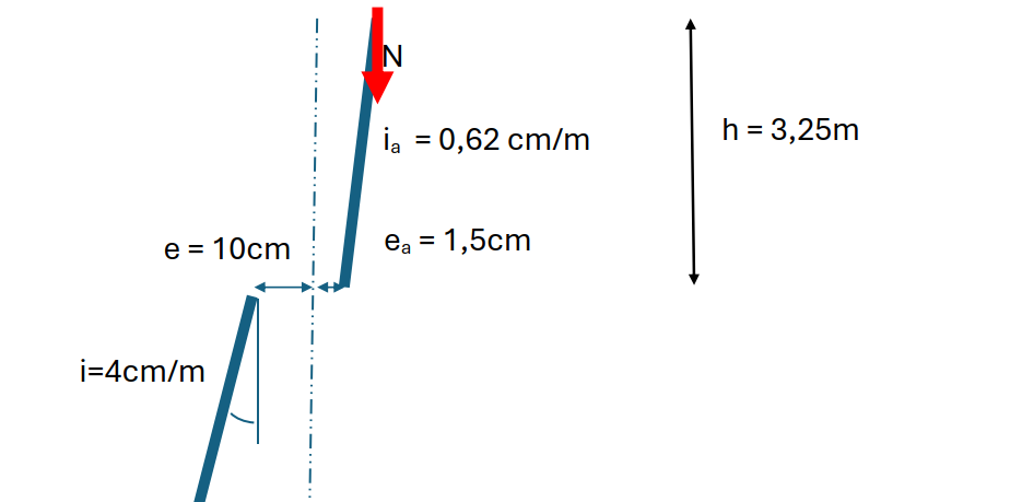
For cast‑in‑place screw piles, NF 12699 §8.2 specifies the following tolerances:
- layout deviation e = 10 cm
- inclination deviation i = 4%
For columns, NF EN 13670 CN applies:
- layout tolerance ea = 1.5 cm
- inclination tolerance corresponding to 2 cm deviation at the top: ia = 0.62%
This is the minimum accidental eccentricity required by EC2 for non‑braced columns, slightly more unfavorable than the execution standard.
Because horizontal restraint is absent at both pile head and column head, and since there is no ground beam at the pile head, layout and inclination deviations generate actions in the {column + pile} system.
These effects are cumulative and concurrent with other horizontal actions. They can occur in any direction, so design must consider the most unfavorable arrangement.
They can be included in the model in two different ways:
- as a “construction camber” following execution tolerances
- as 3 additional point loads on a nominally positioned system:
- horizontal load ia·N at column head
- horizontal load (i − ia)·N at pile head
- moment (e + ea)·N at pile head
We use the first option.
Effect of the diaphragm on execution tolerances
At the column head, the slab may act as a rigid diaphragm between columns, corresponding to EC2 §5.2(5): parallel non‑braced columns.
This clause accounts for the statistical expectation that not all columns will have execution deviations in the same direction and sense.
The studied column—the one with the most unfavorable deviation—may be “helped” by others through the diaphragm. This beneficial effect is represented by a stabilizing horizontal force of −i(1−αm)N (see also this article).
In our study, this beneficial effect is neglected.
Structural assumptions
Partial fixity at column head
Hollow‑core slabs are usually designed as simply supported elements. The shear‑key connections at supports do not include details intended to transfer bending moments.
However, in practice, projecting prestressing strands and the typical reinforcement mesh in the topping slab provide limited rotational stiffness by mobilizing slab flexural stiffness.
Here, we assume that the beam between column head and hollow‑core slab diffuses a portion of the column moment into a length of the beam‑to‑slab interface.
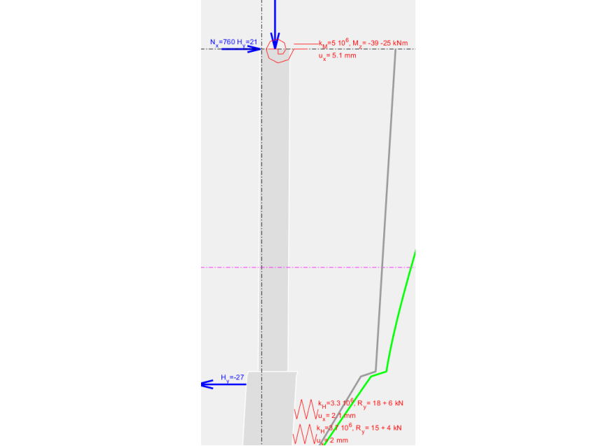
We therefore use a symbolic rotational stiffness of kM = 0.5 × 10⁷ Nm/rad at the column head. We will later check the magnitude of moments transferred to the slabs.
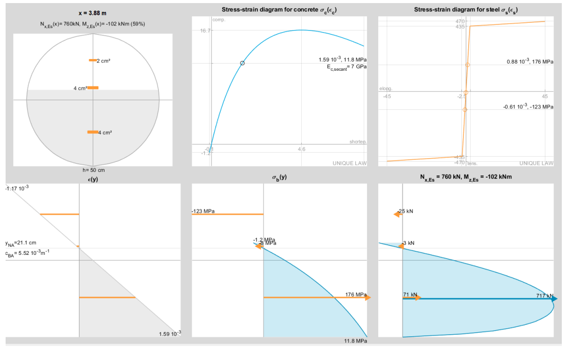
Concrete characteristics
- Column 30×30 cm, C25/30 concrete, reinforced with 4HA12, fyk = 500 MPa, class B.
- Cast‑in‑place screw pile, diameter 50 cm, C25/30 concrete, reinforced with 5HA16, fyk = 500 MPa, class B.
- fck* = 25 / (1.3 × 1.04) = 18.5 MPa
- fcd = 12.3 MPa
Ultimate limit state actions
At the column head, we assume: NELU = 760 kN and HELU = 21 kN.
Creep coefficient of concrete and soil
For long‑term creep:
- K∞ = 0.5 Ki for soil
- Ec,∞ = 0.33 Ecm for concrete
Using the approach described in this article, long‑term effects are derived from gravity loads.
Since the most significant actions come from execution tolerances rather than wind or braking, the long‑term fraction τφ is based on gravity loads:
τφ = EdELS,QP / Ed ≈ (G + ψ2Q) / (1.35G + 1.5Q)
With G = 36 t, Q = 18 t, ψ2 = 0.6 → τφ = 62%
Effective modulus reduction:
ηef = 1 / (1 + τφ (1/η∞ − 1))
For concrete, η∞ = 0.33 → ηef = 0.44 → Ec,ef = 0.44 Ec,i, φef = τφ φ∞ = 1.24
For soil, η∞ = 0.5 → ηef = 0.62 → Kef = 0.62 Ki
Soil characteristics
For a pile‑soil lateral‑load analysis, only limited depth needs modelling since horizontal actions dissipate quickly. Here, a depth of 7 m is considered.
The soil is assumed homogeneous over this depth and composed of silts with pressiometric parameters: Em = 8 MPa, pl* = 0.8 MPa, pf* = 0.5 MPa.
Axial load transfer by skin friction is neglected for simplicity.
The frontal reaction is calculated using Annex I of NF P94‑262 and long‑term effects, giving: kh = 2.2 × 10⁷ N/m/ml. A reduction applies near the surface over a height of 4 pile diameters.
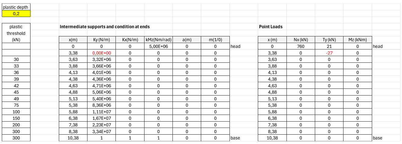
Convention: x is vertical, positive downward.
- x = 0: column head—loads 760 kN and 21 kN
- x = 3.25: column base, pile head, start of soil reaction
Soil is modelled with springs spaced at 25 cm, then 50 cm, 1 m, 2 m.
- x = 3.38: first spring
- x = 10.38: perfect embedment (K = “1” means +∞ in the tool)
Soil plasticity management
Plastic depth is set to 0.2 m → x = 3.45 m. Springs above this depth are removed due to reaching plastic reaction R1.
Numerical simulation
Numerical simulation computes the exact solution of the {pile–soil} system in seconds.
Highlighting second‑order effects
Option “I = f(M)” enables second‑order visualization:
- Graphically: blue = 1st order, green = 2nd order
- Numerically: results shown as “1st order value + 2nd order effect”
Support reactions
Soil plasticity check
Plastic depth assumed: x = 3.45 m.
First spring at x = 3.38 m shows reaction fixed at plastic value R1 = −27 kN. Second spring at x = 3.63 m has stiffness 3.3×10⁶ N/m and plastic limit 30 kN; reaction = 24 kN < 30 kN → model validated.
Moments transferred to hollow‑core slabs
At column head:
- axial displacement = 5.1 mm
- moment transferred to slabs = 39 + 25 = 64 kNm
Depending on the assumed load‑distribution width into two hollow‑core units, this may be acceptable. Here, we assume it is acceptable and the connection model is validated.
If not acceptable, the simulation could be redone with reduced fixity.
Advantages of GIM vs MG1:
- automatic determination of stiffness effects without EC2 formulas or buckling length
- no need to guess critical‑section location
- explicit second‑order support reactions to transmit to adjacent elements
See also Limitations of EC2 General Method.
Global structural analysis
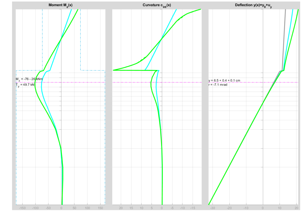
Observations:
- pile critical moment = 76 kNm (1st order) + 26 kNm (2nd order) → +34%
- column base moment = 44 kNm + 24 kNm → +54%
- column head displacement = 4.4 cm + 3.2 cm
Column curvature does not follow moment shape: concrete and steel begin plastifying in compression at both ends.
Local verification of column base
Column base is near ultimate moment; inertia loss is significant. Curvature from section diagram (23.35×10⁻³ m⁻¹) matches curvature cint(x).
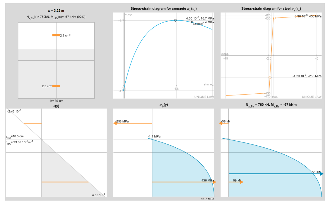
Local verification of pile
The pile section appears to have more margin, but since fcd = 12.3 MPa, it is nevertheless close to the NF P94‑262 limit.