
 FR
FR 
MG1 General Method : Evaluation of the First-Order Moment and End Stiffnesses to Be Considered in the Design of Columns and Walls.
The general method for column design according to Eurocode 2 is an important everyday tool for the reinforced concrete structural engineer. It makes it possible to significantly reduce the theoretical complexity of studying a slender reinforced concrete column or wall, by approximating second-order effects.
However, this method has usage limitations and caution points that can sometimes be difficult to master, especially since spreadsheet implementations—commonly used in design offices—may hide certain important concepts.
This four-part dossier offers a review of the different calculation steps of the general method, with a focus on various influential aspects. This Part 3 details several key caution points regarding the determination of the first-order bending moment to be considered and the evaluation of the boundary stiffnesses to be adopted.
Back to the previous article : General Method of EC2 and Usage Limitations – An Assumption of Elastic Deformation (2/4)
Determining the Appropriate First-Order Moment Consistent with MG1
Case of a Pinned–Pinned Real Column
Let us consider a first example: a real pinned–pinned column corresponding to case a) presented above. Applying MG1 schematically leads to studying the following equivalent mast:
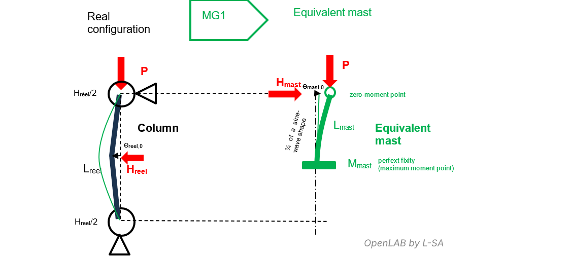
Recall that in MG1, studying the stability of the column in its real configuration is equivalent to studying the stability of this equivalent mast, which itself reduces to studying the base section of the mast.
The pinned–pinned column can be regarded as two mirrored cantilever masts fixed together at their mid-height.
The equivalence between the two models is straightforward:
- free length of the equivalent mast: Lmast = ½ Lreal,
- equivalent initial eccentricity: emast0 = ereal0,
- horizontal load at the top of the mast: Hmast = Hreal/2,
- axial load: P
The first-order moment acting on the fixed base of the mast is therefore:
Mmast1st = emast0·P + Hmast·Lmast.
This moment is equal to the first-order moment at mid-height of the real column:
Mreal1st = ereal0·P + Hreal·Lreal/4 = Mmast1st.
The transition from one model to the other for MG1 is therefore simple and carries no risk of error.
Case of a Partially Fixed Real Mast
If we now examine configuration g’), a simplification of case g), we obtain the following diagram:
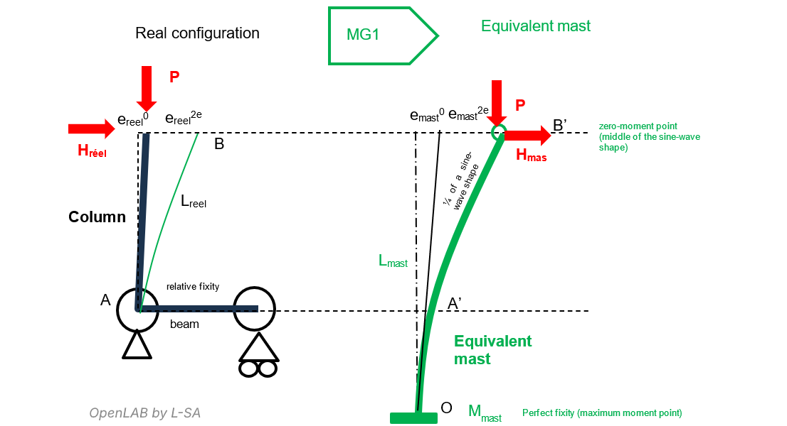
This configuration raises again the question of determining the appropriate first-order moment to use in MG1, and this time the answer is less straightforward. The critical section of the real model is located at A, at the interface where the column is embedded into the beam. The first-order moment is:
Mreal,A1st = ereal0·P + Hreal·Lreal.
One might be tempted to use this moment directly in MG1. This would be incorrect, because in this partially fixed cantilever configuration, the buckling length is greater than twice the real length. In other words, the perfect fixed-base section of the equivalent mast (the one studied in MG1) is located at point O, beyond the real column.
It is better to refer to the diagram on the right to correctly interpret MG1.
Between A’ and B’, the bending moment and the sinusoidal deformation are identical to those between A and B, except for a constant: yA–B(z) = yA’–B’(z) – yA’.
Since the moment at B and B’ is zero, these points correspond to the midpoints of the sinusoid. At O, corresponding to the perfect fixity of the mast, the sinusoid reaches its maximum.
The first-order moment to use in MG1 is therefore the fixed-base moment at O:
Mmast,O1st = emast0·P + Hmast·Lmast, with
- emast0 = ereal0 · (Lmast/Lreal),
- Hmast = Hreal,
- Lmast > Lreal (EC2 formula 5g) can be used to determine the buckling length l0 of the real column; then Lmast = ½ l0),
From Mmast,O1st, MG1 determines the equilibrium point of the critical section, leading to:
{ emasttot = emast0 + emast2nd, Mmast,Otot = Mmast,O1st + Mmast,O2nd }
with Mmast,O2nd = emast2nd·P.
To deduce erealtot at B in the real column and the total moment Mreal,Atot acting on the real base section in A, one must apply the transformation formulas:
- yB’ = emasttot,
- yA’ = emasttot·(1 – sin(π/2 · Lreal / Lmast)),
- erealtot = yB = yB’ − yA’ = emasttot·sin(π/2 · Lreal / Lmast),
- Mreal,Atot = emasttot·P·sin(π/2 · Lreal / Lmast) + Hreal·Lreal < Mmast,Otot
Although the second-order moment at A (the real base) is lower than the second-order moment at O (the fictitious mast base), the reinforcement and formwork at A must reflect the section verified at O. The MG1 assumption requires uniform section properties along the height.
For a practical case of a partially fixed mast, see also our example here: Design of a Mast Using the EC2 General Method – Configuration and Optimisation
Carefully Evaluating Support Stiffnesses
A discreet but important statement appears in EC2 §5.8.3.2 regarding assumed boundary stiffnesses:

Considering boundary stiffnesses is favourable for stability. Therefore, stiffness assumptions must always be conservative. In practice, perfect fixity is difficult to achieve; assuming a flexibility k1 = 0.1 increases the buckling length by 10% as a safety measure.
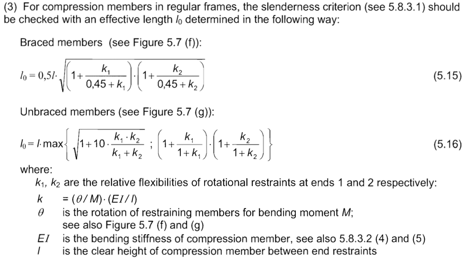
In general, determining boundary stiffness is necessary to evaluate the buckling length when the column does not have pure boundary conditions (free, pinned or perfectly fixed). Eurocode 2 provides formulas for doing so in relation to Figure 5.7.
Departing slightly from EC2 notation, we use “s” for rotational flexibility in rad/N·m and “k” for rotational stiffness in N·m/rad, one being the reciprocal of the other.
Thus, we rewrite the flexibility expression at the end of the column using the following equivalent form:
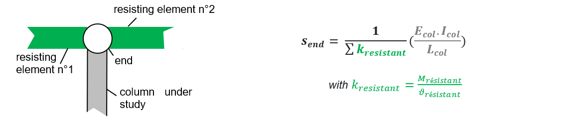
This highlights the additive relationship between contributing stiffness components. kelement may depend on its rotational flexibility.
If the resisting element behaves like an elastic, constant-section beam, the rotational stiffness can be obtained using the classical formula:

The assumption that adjacent elements remain in the elastic domain at ULS should generally hold, but must be verified to avoid overestimating stabilizing contributions.
Two general remarks for a mast fixed into a beam:
1/ **Perfect fixity but partial fixity in the column model**
The connection between the column and the beam may be perfectly rigid, yet appear as partial fixity in the column model because the beam itself rotates under load.

2/ **Destabilizing coupling between column and beam**
Although partial fixity is stabilizing, coupling may introduce a destabilizing effect if the beam carries other loads (e.g. gravity loads). This behaves similarly to a geometric imperfection in the mast example.

If the column is supported at an intermediate support of a continuous beam, this destabilizing effect is usually negligible.
The Concrete Elastic Modulus to Be Used for the Column and Adjacent Elements
To determine boundary flexibility, EC2’s formula assumes the column remains linear elastic at ULS and that its mechanical properties are constant along its height, since E and I appear as unique values in the expression.
This assumption aligns with the simplified MG1 concept (constant, elastic section enabling the sinusoidal deformation assumption and the notion of buckling length).
However, the **value of the concrete modulus “E”** used for the column deserves special attention.
It is not the mean or “likely” concrete behaviour curve used at SLS; instead, the design behaviour curve must be used, capped at fcd rather than fcm.
The graph below helps illustrate the choice of E:
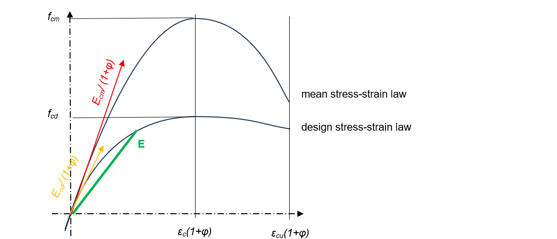
A non-oversized column will likely work beyond its pseudo-elastic behaviour initially represented by Ecd/(1+φ). For boundary flexibility calculations, a significantly lower modulus is therefore more realistic.
For consistency, the design behaviour should also be used for adjacent resisting elements.
In general, overestimating the column modulus E and underestimating cracking or plastification leads to conservative results, as it increases boundary flexibility. Using E = Ecd/(1+φ) for the column is a safe choice.
For beams, however, it is safer to underestimate E. Using the uncracked inertia for the column and the cracked inertia for beams leads to a conservative estimate of the buckling length.
The next part will address several topics often treated “briefly”, such as site tolerances, serviceability deformations and the justification of second-order effects : General Method of EC2 and Usage Limitations – Tolerances, Serviceability, and Finalising the Design (4/4)