
 FR
FR 
Analysis of the MG1 General Method: The Impact of the Deformation Shape on the Design of RC Columns and Walls.
The general method for column design according to Eurocode 2 is an important everyday tool for the reinforced concrete structural engineer. It makes it possible to significantly reduce the theoretical complexity of studying a slender reinforced concrete column or wall, by approximating second-order effects.
However, this method has usage limitations and caution points that can sometimes be difficult to master, especially since spreadsheet implementations—commonly used in design offices—may hide certain important concepts.
This four-part dossier offers a review of the different calculation steps of the general method, with a focus on various influential aspects. This Part 2 provides a focus on one of the underlying assumptions of the method: the shape of the deformation.
Back to the previous article : General Method of EC2 and Usage Limitations – Principles of the Method (1/4)
Making an Assumption Regarding the Shape of the Deformation
MG1 therefore generally requires adopting an assumption about the deformation shape of the column, one that should resemble as closely as possible the real solution to the problem. Most often, a sinusoidal assumption is adopted, which corresponds for the equivalent mast to a quarter sine wave.
We have seen that this sinusoidal shape corresponds to the exact solution of a mast:
- for which the first-order bending moment is negligible compared to the second-order moment,
- which has a constant bi-symmetric cross-section along its axis,
- with elastic material behaviour (uncracked and linear modulus),
- subject exclusively to a single axial load at the top,
However, when in its real environment:
- the column is subjected to a significant or even predominant first-order moment,
- it cracks or plastifies in its most solicited sections (as often sought in ULS design),
- its inertia varies (formwork or reinforcement changes),
- or under successive axial loads,
the sinusoidal deformation assumption may be far from the real solution.
The figure below shows the case of a single 3 m mast subjected to lateral loading in three different configurations. Values are chosen so that the first-order bending moment and axial force at the fixed base are identical in all three cases.
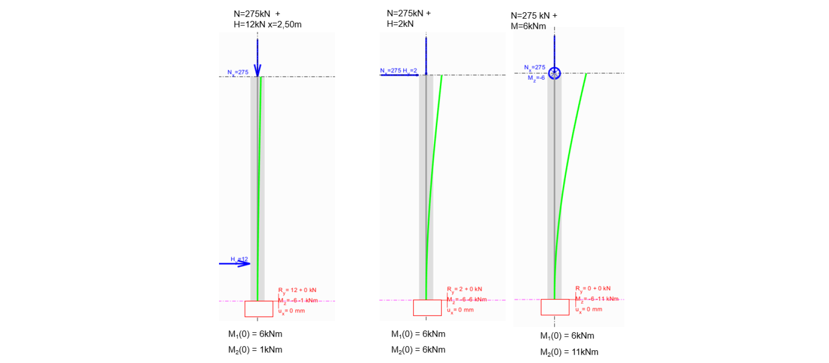
The exact second-order solution differs greatly in the three cases, and even though the axial load, first-order base moment, and the columns themselves are strictly identical, the deformation and therefore the resulting second-order moment vary by a factor of 1 to 10.
A first-order analysis already shows the significant difference in deformation across the three configurations.
Yet, if MG1 is used with a sinusoidal deformation assumption, the result would be identical for all three configurations.
More broadly, when MG1 is applied to column configurations with varied loads or boundary conditions (eccentric loads, partial fixity), the method moves further away from its original assumptions.
The engineer’s skill lies in correctly mastering the limits of the model to determine the appropriate “reduced model” and appropriate deformation assumption.
Representation of Geometric Imperfection
Regardless of the deformation induced in a column by loading, the “construction deflections” of a reinforced concrete column are initial imperfections that generate bending effects from the first-order and may initiate second-order effects (their buckling mode and direction).
These initial imperfections must therefore be included in the calculation. They can arise from two distinct sources:
- intentional geometric shapes of the column’s centerline, chosen for architectural, functional, or structural reasons,
- geometric imperfections due to construction tolerances (reinforcement or formwork positioning), unavoidable on site,
Eurocode 2 §5.2 provides the values of these geometric imperfections to include upfront, ensuring that column verification is consistent with execution tolerances that will be permitted during construction.
Figure 5.1 illustrates more precisely this concept when studying a cantilever or pinned–pinned column.
It also proposes an alternative consisting of replacing the geometric imperfection in the model with an equivalent horizontal force Hi.
The diagrams 1 to 4 reproduced below come directly from Eurocode figure 5.1, and diagrams 5 and 6 have been added for illustration.
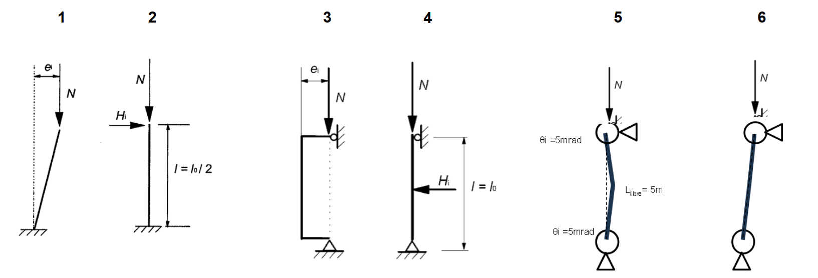
Diagrams 1 and 2 both create a triangular bending moment distribution from the top to the fixed base. Adopting diagram 2 with Hi = ϑi·N is equivalent to diagram 1 with ei = ϑi·L.
However, diagrams 3 and 4 highlight a bias in understanding the general method through the lens of MG1, which is only a simplified option of the full general method.
Indeed, as shown earlier, diagrams 3 and 4 are not equivalent: diagram 3 yields a constant bending moment M = ϑi·Li/2 · N along the height, while diagram 4, used with Hi = 2 ϑi·N, gives a bi-triangular bending moment distribution with the same maximum moment M = ϑi·Li/2·N.
The difference between cases 3 and 4 arises for the same reasons as the differences seen earlier between the three 3 m column configurations.
Diagram 6 illustrates the common case of a verticality error in a pinned–pinned column. Unlike case 1, this imperfection does not generate any bending moment, because the two end supports can resist the horizontal reaction required to realign the axial force with the column’s inclination.
A Curvature Shape Similar to the First-Order Moment
As an alternative to the sinusoidal assumption, Eurocode 2 §5.8.6(6) explicitly proposes assuming a curvature shape similar to the first-order bending moment. However, this approach is not necessarily easier to validate.
Consider the mast case with a top moment (third case above):
- The ULS first-order moment is constant along the height,
- Therefore curvature is assumed constant,
- Hence the deformation y(x), being the integral of curvature twice, is parabolic,
But once second-order effects appear:
- the second-order moment is no longer constant,
- the section most often is no longer elastic,
- and the final deformation cannot be parabolic.
Since MG1 requires an assumption on the *final* deformation, we end up assuming a parabolic shape that in reality cannot occur.
Determining the Buckling Length
For the remainder of this document, we assume the sinusoidal deformation hypothesis applies.
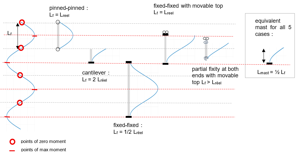
The transition from the column in its real configuration to its equivalent mast model requires determining the so-called “effective length” per EC2, also known as the buckling length of the real column. This buckling length corresponds to the length of the element (possibly extended fictitiously) over which the deformation completes exactly half a sine wave.
The following illustration shows five column configurations sharing the same buckling length and therefore studied with the same equivalent mast model within MG1, despite different real lengths Lreel and various support conditions.
Eurocode 2 Figure 5.7 offers another representation of the same concept, with seven columns sharing the same real length:
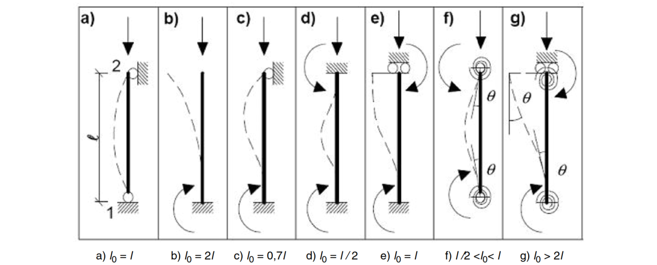
For the purpose of this document, this EC2 figure is reorganized as follows:
- classification according to boundary conditions,
- addition of cases g’) and g’’), which are specific cases of g),
- highlighting zero-moment locations and critical sections,
- correcting formula “g) l0 > 2 l” into “g) l0 > l”, since l0 > 2 l applies strictly to g’),
- notation Lf instead of l0 for buckling/effective lengths,
- notation s instead of k to denote support flexibilities,
The critical sections identified correspond to those evaluated in the equivalent mast model used within MG1.
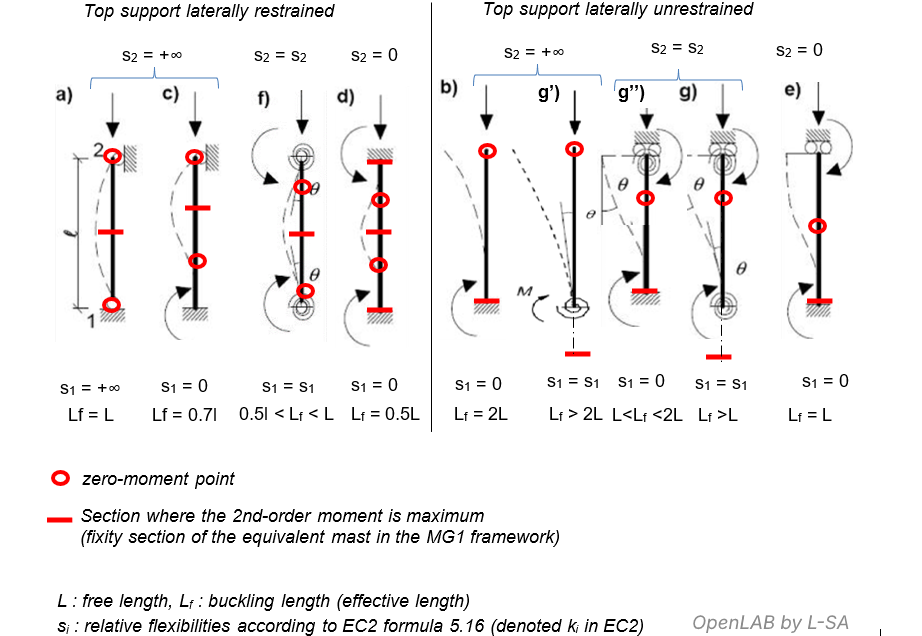
It can already be noted that in some support configurations, the critical section is located beyond the real column. The challenge then is determining the correct first-order moment to use in the equivalent mast model under the MG1 assumption.
This is addressed in the next chapter : General Method of EC2 and Usage Limitations – Lateral Loads and Support Stiffnesses (3/4)