
 FR
FR 
An approach to analyzing and designing horizontal structures subjected to shrinkage
Eurocode 2 is relatively precise in determining the evolution of concrete shrinkage over time. However, it remains much more succinct regarding how to incorporate this phenomenon into reinforced concrete design calculations.
Beyond deformations alone, the engineer is often faced with determining bending moments, axial forces, stresses in reinforcement, as well as crack widths, particularly in restrained shrinkage configurations.
The example presented below shows how the General Integral Method (GIM) makes it possible to capture physical phenomena that are often anticipated but difficult to access using conventional approaches. It progressively highlights:
- axial elongation under gravity loads,
- reduction of the cracking moment due to shrinkage,
- increase in curvatures and deflections,
- as well as the determination of tensile force in cases of restrained shrinkage.
System presentation
In this article, we consider a 28 cm thick reinforced concrete continuous slab, consisting of three spans of 7.50 m (center-to-center), monolithically supported on supports 30 cm wide.
In addition to its self-weight g0 = 700 kg/m², the slab carries the following loads:
- permanent loads : g = 100 kg/m²
- live loads : q = 500 kg/m², ψ2 = 0.6.
The slab is made of C25/30 concrete, with exposure class XC1, reinforcement cover set at 2.5 cm, and long-term creep assumed equal to ϕinf = 2.
The reinforcement is class B500 steel, and the slab reinforcement has been designed at ULS using linear elastic analysis, without redistribution (i.e., according to EC2 §5.4).
The following reinforcement is thus adopted:
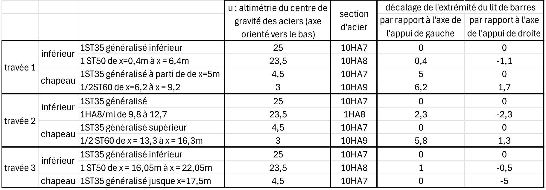
Total deflection under SLS QP
The total deflection, assessed in the long term under quasi-permanent SLS loading, must satisfy the criterion L/250 = 3 cm.
For our floor configuration, the loading scenario leading to the worst deflection case is the loaded–unloaded–loaded condition.
The loading is therefore defined as follows:
- span 1 and 3 : loaded : (g0 + g) + ψ2q = 1100 kg/m²
- span 2 : unloaded (g0 + g) = 800 kg/m²
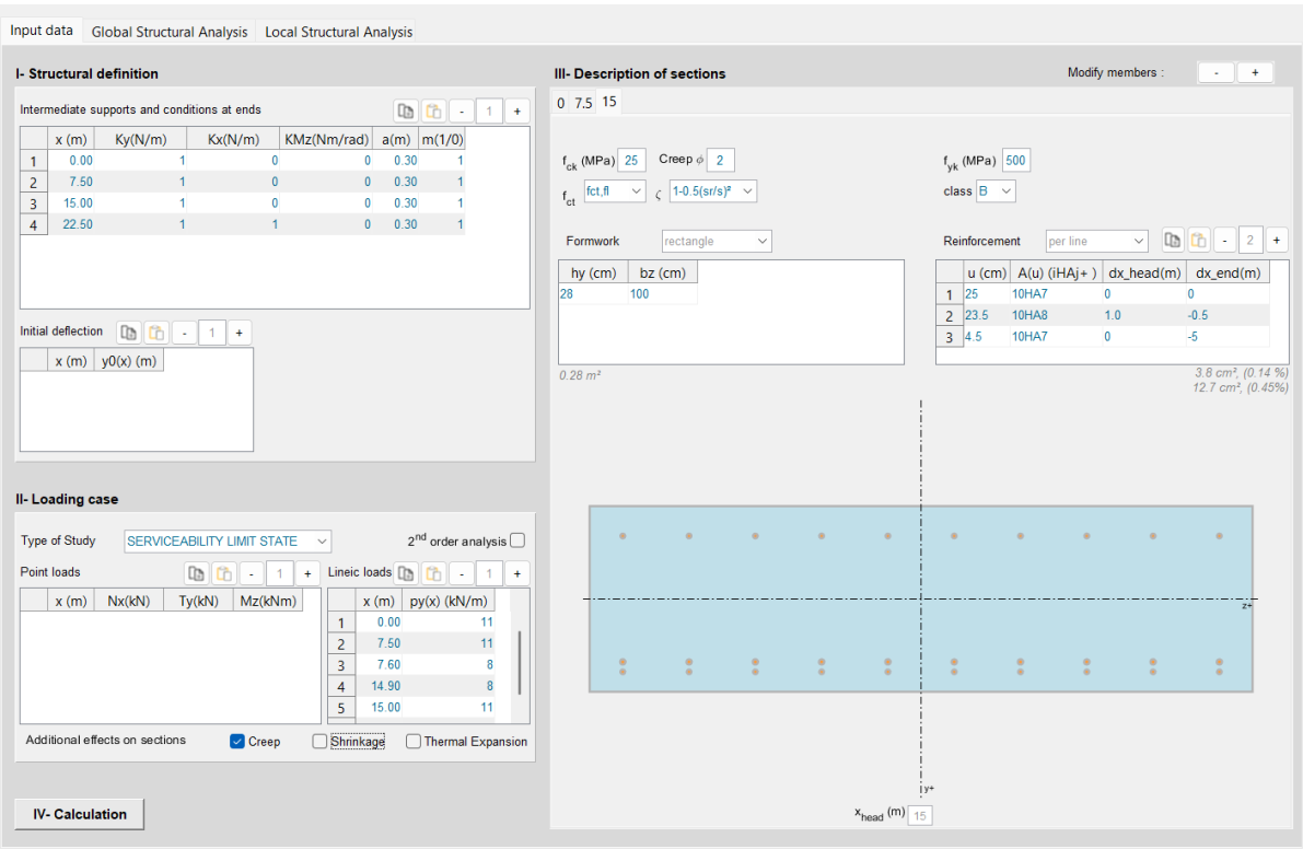
The model setup is described in the input data tab as follows:
The structural analysis yields the following results:
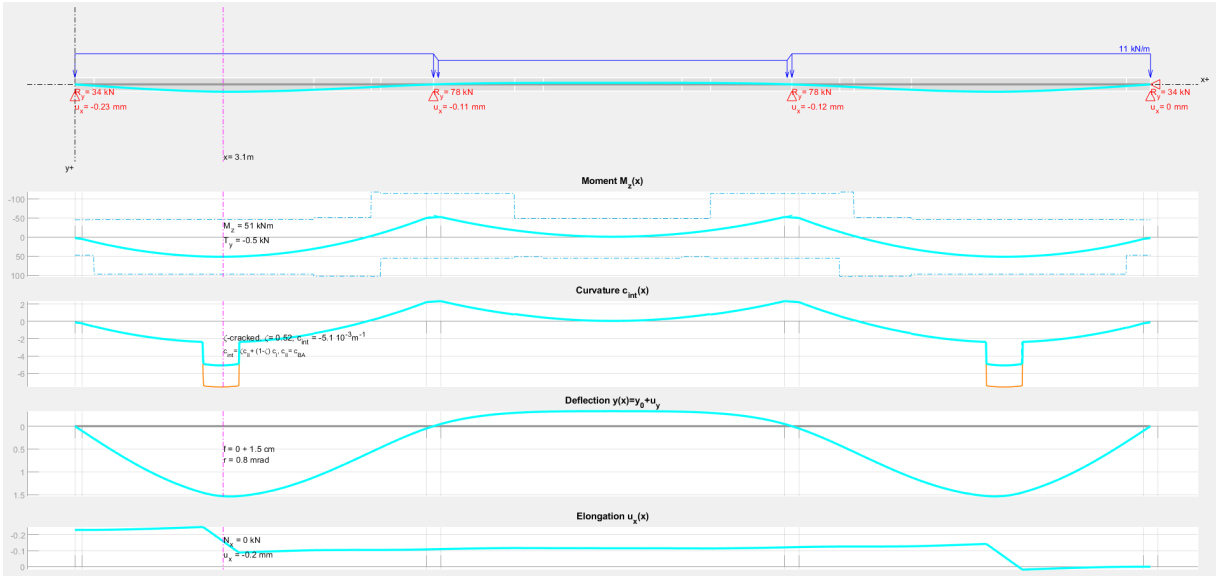
This first simulation gives a deflection of 1.5 cm. It can be noted that under this loading condition, only the edge-span sections crack.
As a result, the slab globally retains good stiffness and largely satisfies the criterion (1.5 cm < 3 cm).
Elongation under gravity loads
With a view to later incorporating the effect of shrinkage, we now introduce the curve of slab elongation under gravity loading. The model includes a single axial restraint at the right-end support, so that the displacement ux of the left support shows the total axial shortening (positive) or elongation (negative) of the slab. The calculation shows here an elongation of 0.23 mm under this quasi-permanent loading condition, mainly due to the two cracked zones as illustrated by the evolution of the curve ux(x).
This elongation is a normal phenomenon inherent to reinforced concrete behavior (see also here for a detailed discussion), and its evaluation is necessary before addressing the effects of restrained shrinkage.
ζ-cracking
The cracking state of the section in span can be examined more precisely:
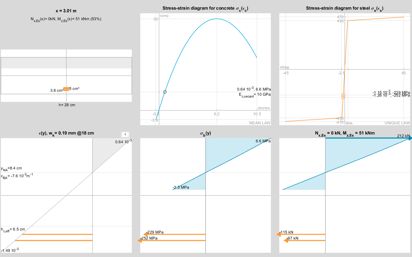
In the local representation, the curvature of the RC section is cRC = 7.59 10-3 m-1. This is greater than the internal curvature used in the structural analysis (5.1 10-3 m-1).
This difference is explained by the fact that under a moment of 51 kNm, the slab only “begins” to crack; cracking is not yet widespread in this zone. Eurocode 2 introduces the coefficient ζ (formula 7.19) to account for this effect. Here ζ = 0.52 (see also here on the topic of ζ-cracking).
Crack width and spacing
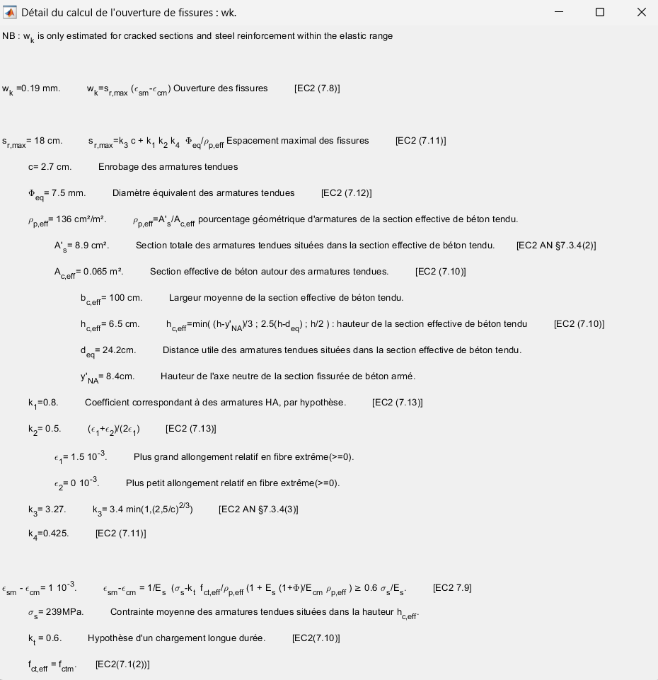
The crack width calculation for this same critical section gives a crack opening wk = 0.2 mm and a spacing of 19 cm, obtained in detail as follows:
Effect of “unrestrained” shrinkage
The study of total deflection is conventionally carried out in the long term under quasi-permanent SLS loading. It is therefore consistent to integrate shrinkage in the same way, especially since shrinkage affects deflections by increasing deformations in flexural members, whether restrained or not and regardless of their length.
Eurocode 2 provides formula (7.21), which allows the effect of shrinkage on section curvature to be determined in the “unrestrained” case. Unfortunately, this formula is strictly applicable only to statically determinate beams (see also the conditions of application of formula 7.21 here).
In our configuration, the GIM incorporates shrinkage directly into the concrete constitutive law, making it possible to handle the desired statically indeterminate situation (see also this article on the subject).
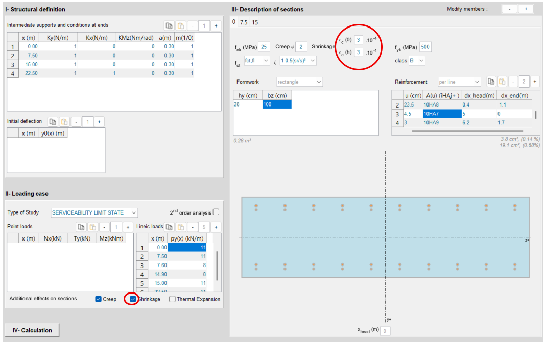
Calculation result
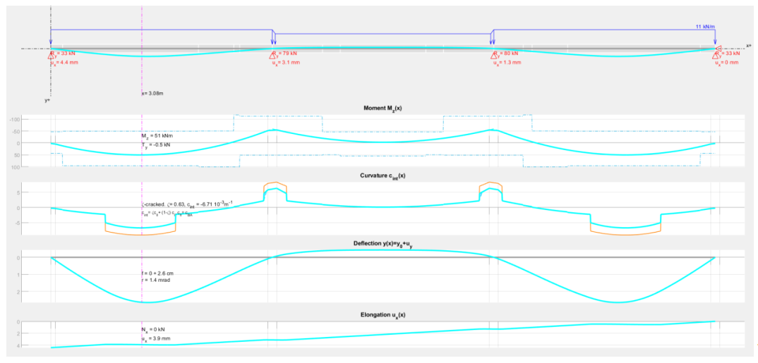
While keeping the same loading case, the inclusion of concrete shrinkage leads to the following phenomena:
Reduction of Mcr and increase of cracked lengths
Shrinkage leads to a clear reduction of the cracking moment.
To understand this phenomenon, the diagrams below reproduce the mechanical scheme of a concrete section resisting 45 kNm, before and after shrinkage.
Due to shrinkage, all reinforcement is in compression. To balance the same bending moment, the tensile concrete is therefore more heavily mobilized and reaches fctm,fl (cracking threshold) more quickly.
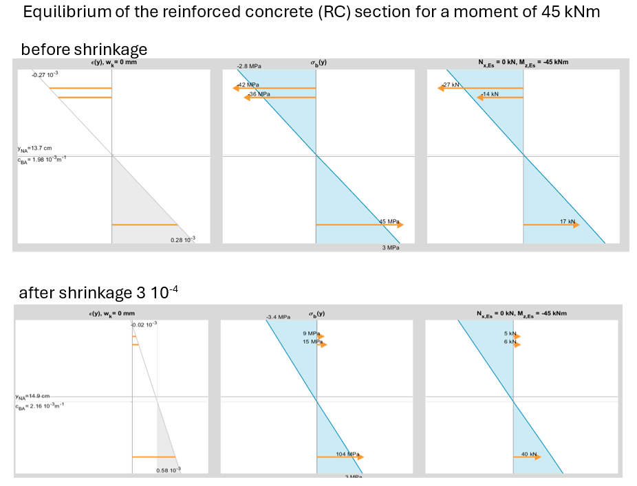
In the lower diagram, fctm,fl is reached; the scheme corresponds exactly to the point just before cracking: the cracking moment after shrinkage is therefore 45 kNm. In the upper diagram, without shrinkage, the tensile concrete still has a reserve (2.8 MPa < 3.4 MPa) before reaching the cracking threshold.
Note: Within the framework of EC2 §7.4.3(6), formula (7.21), Eurocode 2 proposes to keep the same cracking ratio ζ along the beam after shrinkage, which does not allow this phenomenon to be represented.
Increase in curvature of cracked sections
When the section is cracked, in order to balance the same bending moment, the curvature must increase to mobilize sufficient compressive reaction from the concrete.
The local analysis of the critical section in the edge span evolves as follows:
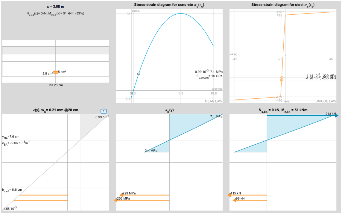
We observe:
- an increase in compressive concrete strain from ε = 0.63 10-3 to 0.99 10-3
- an increase in section curvature from 5.9 10-3 m-1 to 9.06 10-3 m-1
Increase in deflection
The two previously described phenomena:
- reduction of the cracking threshold and increase in cracked length
- increase in the curvature of cracked sections
jointly lead to an increase in deflection from 1.5 cm to 2.6 cm in this example. The deflection criterion remains satisfied (2.6 cm < 3 cm), but with much less margin than before.
Axial shortening of the slab
The model is axially restrained at the right support. It can be seen that shrinkage leads to a displacement of the left support of 4.4 mm, corresponding to the overall shortening of the slab.
Elastic modelling δL = ε·L
If the 28 cm slab were unreinforced concrete placed on a perfectly sliding surface, its shortening could be estimated as δL = ε·L = 3 10-4 · 3×7.5 = 6.75 mm.
This is also what would be observed when modeling the slab with standard finite element software by applying a temperature decrease of 30°C.
Note: Since the bar is elastic, homogeneous, and uncracked, shrinkage can indeed be simulated as a thermal strain effect: εth = −αc·ΔT = 10·10-6 K-1 · 30°C = 3·10-4.
In reality, two phenomena—typically not captured by standard finite element software—reduce the axial shortening effect of the slab:
- along the entire length, the reinforcement partially restrains concrete shortening by developing compressive stresses (see also this article)
- in cracked zones, the shrinkage-induced shortening is fully offset by the elongation due to gravity loads described earlier; these segments even remain slightly elongated
Study of “restrained” shrinkage
Tension in the slab
Simulating the case of a slab axially restrained consists in iteratively determining the axial reaction force to be applied at the left support so as to obtain zero displacement at this same support.
By iteration, a tensile force of 190 kN/m is obtained, leading to the following structural analysis:
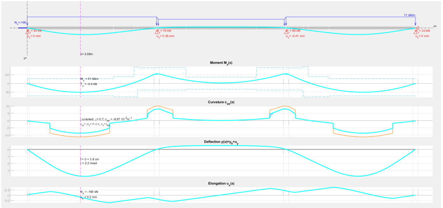
Elastic modelling N = E·S·ε
Assuming the slab behaves as a linear elastic material, the axial force at the left support can be directly deduced from Hooke’s law. Considering:
- a creep-reduced modulus E = 1010 Pa
- a section assumed cracked over half the length, i.e.:
S = 50% × Suncracked + 50% × Scracked
= 50% × 0.28 m² + 50% × 0.095 m²
= 0.14 m²
- a shrinkage strain ε = 3 10-4
we obtain an axial force N = 420 kN/m.
This is almost three times the force obtained when using EC2 constitutive relationships (190 kN/m).
The explanation lies in the phenomena already mentioned: a linear elastic model cannot ensure axial strain compatibility, capture elongation under gravity loads, progressive cracking, etc., and is therefore not always suitable for analyzing shrinkage effects or, more generally, axially restrained reinforced concrete systems.
Further reduction of Mcr and increase in deflection
Axial restraint accentuates the reduction of the cracking moment described earlier due to the tensile axial force. This leads to a further increase in deflection, reaching 3.6 cm, which exceeds the criterion (3 cm).
Increase in crack width and stresses in reinforcement
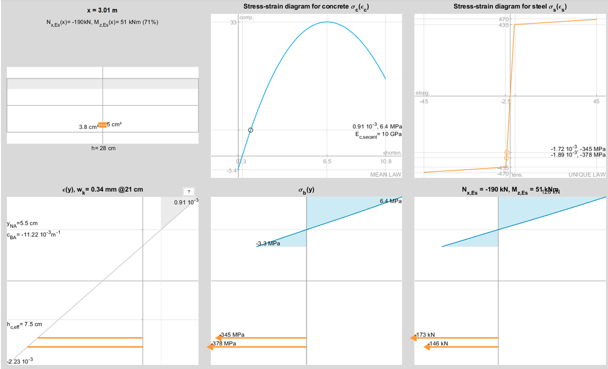
At the critical section, the tensile stress in reinforcement increases by about 120 MPa, and the crack width increases from 0.21 mm to 0.34 mm, as shown below:
Resilience of the slab under SLS loading
In this section, we consider the same configuration as before:
- continuous slab
- loaded–unloaded–loaded SLS case
- creep ϕ = 2
- shrinkage ε = 3 10-4, restrained at end supports
and we examine the sensitivity of the reinforced concrete slab to SLS load variations. The following cases are analyzed:
- G only
- G + ψ2Q (previously presented)
- G + Q
The simulation results are summarized in the table below.
It is observed that the more the slab is loaded, the greater the bending moment, the more cracking occurs, and the more the tensile force in the slab is “released.”
The axial force thus evolves from 289 kN/m under G, to 190 kN/m under G + ψ2Q, and finally to 120 kN/m under G + Q.
In this simulation, the tensile stress in reinforcement and the crack width remain практически unchanged regardless of the SLS loading level.
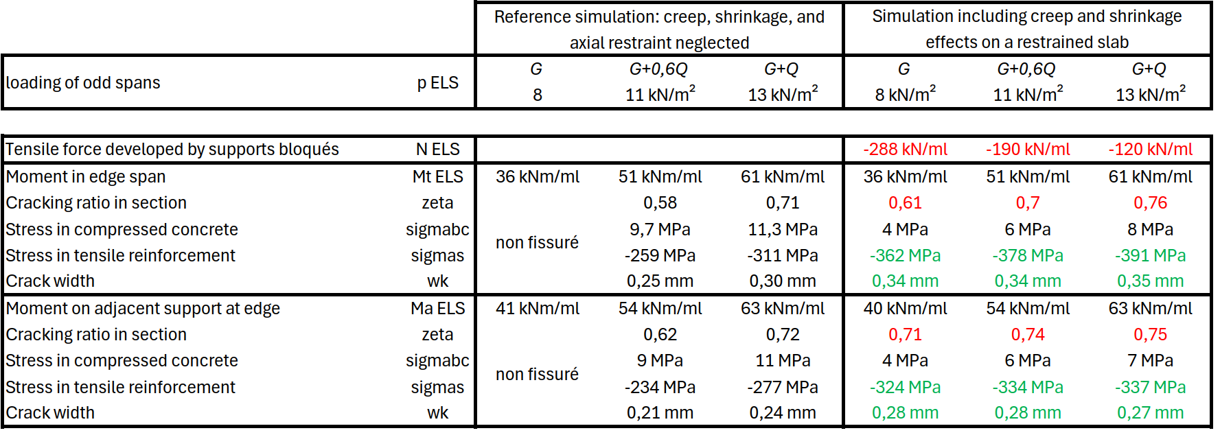
This result appears to highlight a form of “resilience” of reinforced concrete structures in the presence of restrained shrinkage.
