
 FR
FR 
Residential and office buildings in reinforced concrete dating from the post‑war Reconstruction period (1945–1960) were not always designed with explicit consideration of lateral stability. In some buildings of that era, global bracing relies almost entirely on the hyperstatic continuity provided by beam‑column joints and shear keys, which are often lightly reinforced.
This example presents the analysis and justification of a flexible R+5 reinforced concrete frame building subjected to wind actions, which can be reduced to the study of a continuous reinforced concrete column, unbraced, loaded, and partially fixed at each floor level.
The calculation illustrates the benefits of the Integral General Method for addressing this type of configuration with full accuracy, including second‑order effects.
Description of the example
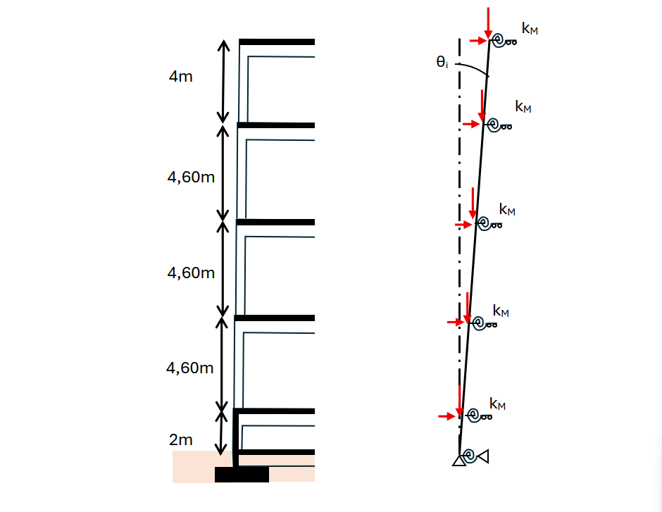
The structure studied is a reinforced concrete building constructed in the 1950s for industrial laboratory use. Its structure consists of a raised ground floor over a crawl space, complemented by 3 storeys of relatively large height (4 m to 4.60 m) to allow the installation of large technical service plenums beneath the slabs.
The floor beams are arranged transversely to the façades and are interrupted in the central area along the circulation zone. The resulting configuration ensures easy routing of services and ducts from the longitudinal axis and then via lateral distribution, without any beam crossings.
The façades, not shown on the plan below, are constructed using prefabricated self-supporting spandrel panels spanning from column to column, completed by glazed aluminium window assemblies.
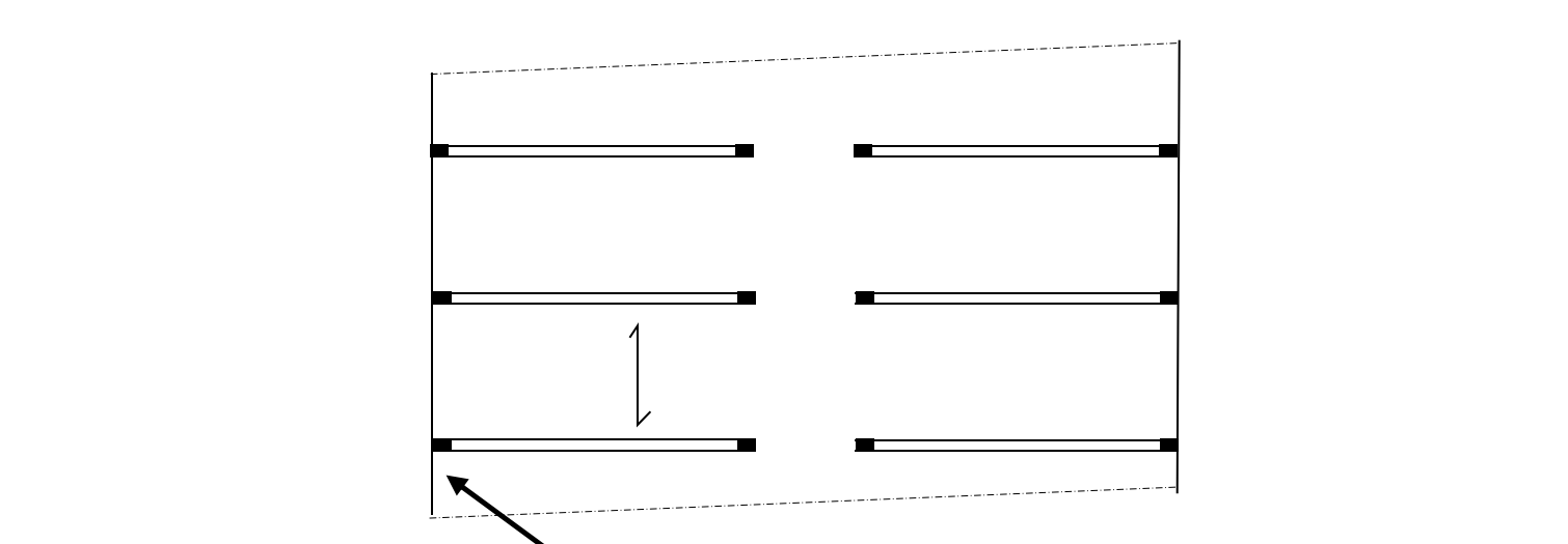
The studied block has no vertical circulation (stair or lift core); access to the floors is provided from adjacent blocks, located on either side of expansion joints.
Bracing of the building under wind acting along the “long side” can therefore only be ensured by the column–beam–column assemblies, each acting as a frame and taking up part of the wind load through distribution via the slabs.
It is possible that the original designer intentionally studied the global stability of the building using these frames, in order to completely free the floor plates from any shear walls.
It is also possible that wind loads were simply not considered, at a time prior to NV65 when the regulatory framework was less established than it is today with regard to these aspects.
In the direction of wind acting on the “gable”, some longitudinal walls are present and provide bracing.
This article presents an EC2-compliant study to verify the global stability of the building under wind acting along the “long side”, in the context of a rehabilitation or vertical extension of the building.
Second-order global stability analysis
Cases where global second-order stability analysis may be omitted
The relative flexibility of such a system alerts the designer to the likely sensitivity of the structure to global second-order effects.
EC2 proposes two criteria that may allow the designer to omit the global stability analysis. These two approaches are examined first before addressing the detailed calculation.
- 5.8.2.(6) states that global second-order effects may be neglected if they represent less than 10% of first-order effects.
Unfortunately, this clause is not self-sufficient. Indeed, it is necessary to compute an upper bound of the second-order effect in order to determine whether its detailed calculation can be omitted.
- 5.8.3.3 provides a formula linking the vertical load, the flexural stiffness of the bracing system, and the height of the structure.
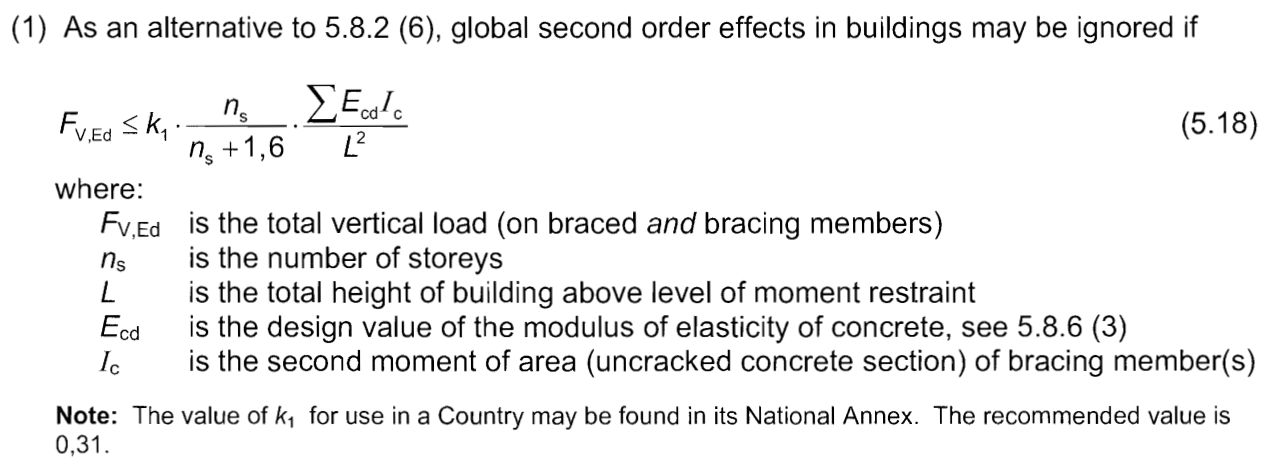
This formula appears interesting, but it is applicable only to wall-braced systems, free at the top and fixed at the foundation, which is not our case.
Out of curiosity, the frame of our project can be replaced by a wall supporting the same vertical load, in order to determine the minimum length of this wall that would exactly satisfy criterion (5.18).
The gravity load acting on one bracing frame is: FV,Ed = 2 × 85 t = 170 t, while the other parameters are: ns = 4, Ecd = 30 GPa / 1.2 / (1 + 1.5) = 10 GPa, L = 20 m.
In our example, the calculation shows that equality is reached for a wall 18 cm thick and 2.75 m long.
Ultimately, the EC2 exemption criteria do not allow avoidance of the second-order global stability analysis for our multi-storey reinforced concrete frame configuration.
The remainder of the article is therefore devoted to this exercise.
Application of Eurocode 2 – §5.8.2 (2)P
EC2 §5.8.2 (2)P states: “when second-order effects are taken into account, equilibrium and resistance shall be verified in the deformed state. Deformations shall be calculated taking into account the appropriate effects of cracking, non-linear material behaviour and creep.”
In addition to accounting for second-order non-linearity, solving the global stability problem necessarily also requires taking into account the non-linear behaviour of concrete and steel, as well as cracking.
Which buckling length* should be adopted for these columns?
* buckling length also referred to as “effective length” or l0 according to EC2 notation
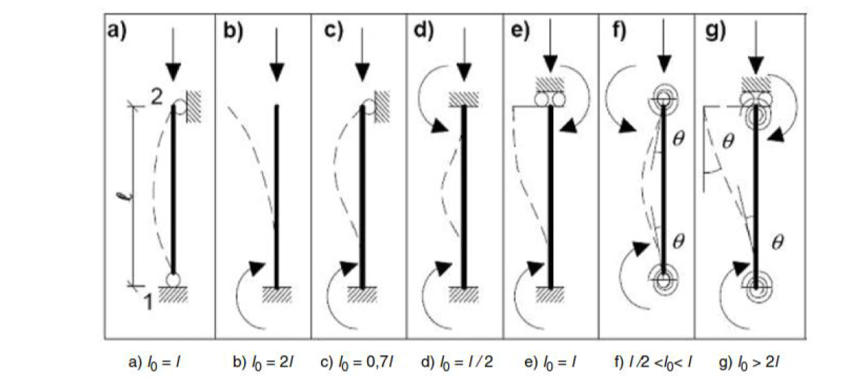
In general, for a reinforced concrete building, the engineer’s intuition is to assume a pin-ended column, braced at the top (Figure 5.7a of EC2), with a buckling length corresponding to the storey height.
This assumption is very often applicable in practice, possibly adjusted to account for partial or full end fixity (Figures c), d), f)).
In rarer cases, when no external bracing is present, the column itself must provide head bracing (end 2 in the diagram): the column is then referred to as “unbraced”, or equivalently a “bracing column”. One of the mechanical models b), e), or g) is then adopted.
The question therefore arises quite quickly: which mechanical model should be applied in our example, and which buckling length should be adopted?
In reality, this question has no answer: here, the very notion of buckling length does not exist!
This statement requires some explanation:
The buckling length is linked to the idea that the column can be considered as an isolated element, loaded only at its ends and supported solely at those ends.
In our example, it is not possible to isolate the columns storey by storey: the deformation of each influences the forces in all the others through continuity and second-order effects; the slabs do not brace the columns, and the axial and transverse loading of the global column is progressive.
Practical methods used by the structural engineer
Traditionally, the structural engineer has two analytical tools available for columns:
- A practical tool for isolated elements: the simplified general method MG1 (also known as the Faessel method), which allows compliance with EC2 §5.8.2 (2)P requirements by approximating deformation compatibility and non-linear section behaviour.
- however, as stated, our case cannot be reduced to an isolated element.
- A global elastic structural analysis tool, based on the finite element method, which allows the study of such structures assuming elastic, homogeneous sections, without accounting for second-order effects.
- this tool cannot be used here, as EC2 §5.8.2 (2)P requires consideration of non-linearity.
Our situation therefore corresponds to a specific case, for which the only suitable solution lies in the use of EC2 §5.7 through a non-linear analysis.
The Integral General Method (IGM) belongs to this category and provides a simple way to address this type of use case:
- without requiring a buckling length,
- without risky simplifications,
- without complex finite element software parameterisation to capture the specificities of this case.
The IGM tool determines the exact solution of the problem, strictly complying with EC2 material laws and integrating second-order effects. It also presents results in a professional format that is fully understandable and verifiable by the practitioner (for more details on this method, see also: IGM).
This is the methodological option adopted for the remainder of this study.
Study parameters
The present section does not detail the establishment of all assumptions of the example, but develops several aspects that are of particular interest in this type of analysis.
Concrete and steel strength parameters
In our example, it is assumed that the strength of the concrete and reinforcement steel of the columns has been assessed, allowing the following values to be adopted:
- fck = 20 MPa for concrete
- fyk = 400 MPa, grade A, for reinforcement steel
In rehabilitation projects, it is worth noting that Annex A of Eurocode 2 allows, where applicable, a 10% increase in steel strength and a 15% increase in concrete strength, through a modification of the partial safety factors related to materials, provided that certain conditions are met regarding the level of knowledge of the existing structure.
Concrete creep coefficient
It is assumed that the proportion of long-term gravity loads is 80%, and that the forces in the column are mainly governed by gravity loads compared with wind effects.
It is also assumed that the concrete creep coefficient at infinite time is ϕinf = 2.
Since the global stability analysis is carried out at ULS, an effective creep coefficient of ϕef = 1.16 is therefore adopted.
NB: Although LT = 80%, at ULS, ϕef ≠ 80% ϕinf; see the section creep coefficient at ULS for more details on this topic.
Geometric imperfection of the structure
Strictly speaking, it is possible to carry out a geometric survey of the building to determine any out-of-plumb condition of each column and to retain the value of the most unfavourable column.
In this example, we consider the procedure to be adopted in the absence of such a survey, or when studying a new structure.
The code-prescribed geometric imperfection is expressed in the form of a global column inclination θi associated with formula (5.1):
θi = θ0 · αh · αm
where θ0 = 5 mrad, and where the following values are adopted:
- total column height L with 2/3 ≤ αh = 2 / L1/2 ≤ 1
- number m of columns participating in bracing αm = (0.5 (1 + 1/m))1/2
In our configuration, the following values may be adopted:
- L = 20 m ⇒ αh = 0.44 -> 0,67
- m = 40 columns ⇒ αm = 0.72
thus θi = 0.005 · 0.67 · 0.72 = 0.0024 rad.
At L = 20 m, a geometric imperfection of 4,8 cm is therefore adopted.
It should be noted that this value is small and, a priori, only weakly penalising for the calculation.
Flexural stiffness of beams acting on the columns
The modelling requires the determination of the flexural stiffness exerted by the beams on the column. These are rotational stiffnesses expressed in Nm/rad, opposing the rotation of the column section at the node by developing a reaction moment opposite to the rotation. On the other hand, these beams do not oppose lateral displacement.
Unlike the case of a beam fixed at one end and free at the other, in our case the beam is fixed at both ends. When a horizontal load acts on the frame, identical moments appear at the tops of both columns, and the point of zero moment is therefore located at mid-span. Everything happens as if the beam were twice as stiff, or equivalently, as if it had a span twice as short.
In our example, this stiffness is assumed to be kM = 3 × 10⁷ Nm/rad.
For a detailed calculation of this stiffness, reference may also be made to this section which recalls the elementary formula applicable in strength of materials and also specifies the value of the modulus E and inertia I to be adopted in a reinforced concrete configuration analysed at ULS.
Support table of the continuous column
Based on the previous estimation, the support table is filled in as follows:
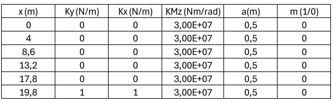
It is recalled that x is the descending longitudinal axis, with zero located at the column head, and y is the lateral axis of the column. The six supports present the flexural stiffness kMz established previously. The lower support is the only one that restrains horizontal and vertical translation of the column (“1” conventionally meaning +∞ in the tool).
The column supports are considered non-monolithic (m = 0) and of width 50 cm (a = 0.5 m).
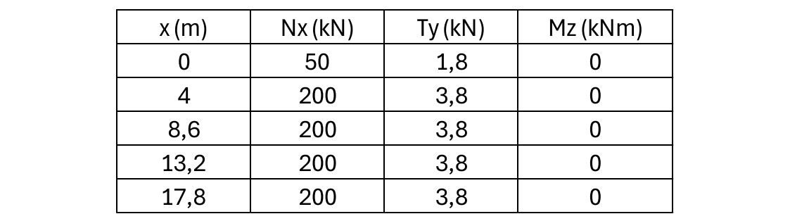
Action table for the continuous column
Finally, it is assumed that the following factored actions apply to the continuous column in the ULS configuration studied. Each node at a typical level receives a gravity load of 200 kN corresponding to the beam reaction and the weight of one façade level, as well as a horizontal force of 3.8 kN corresponding to the share of long-side wind at that level carried by the studied column.
Modelling and results
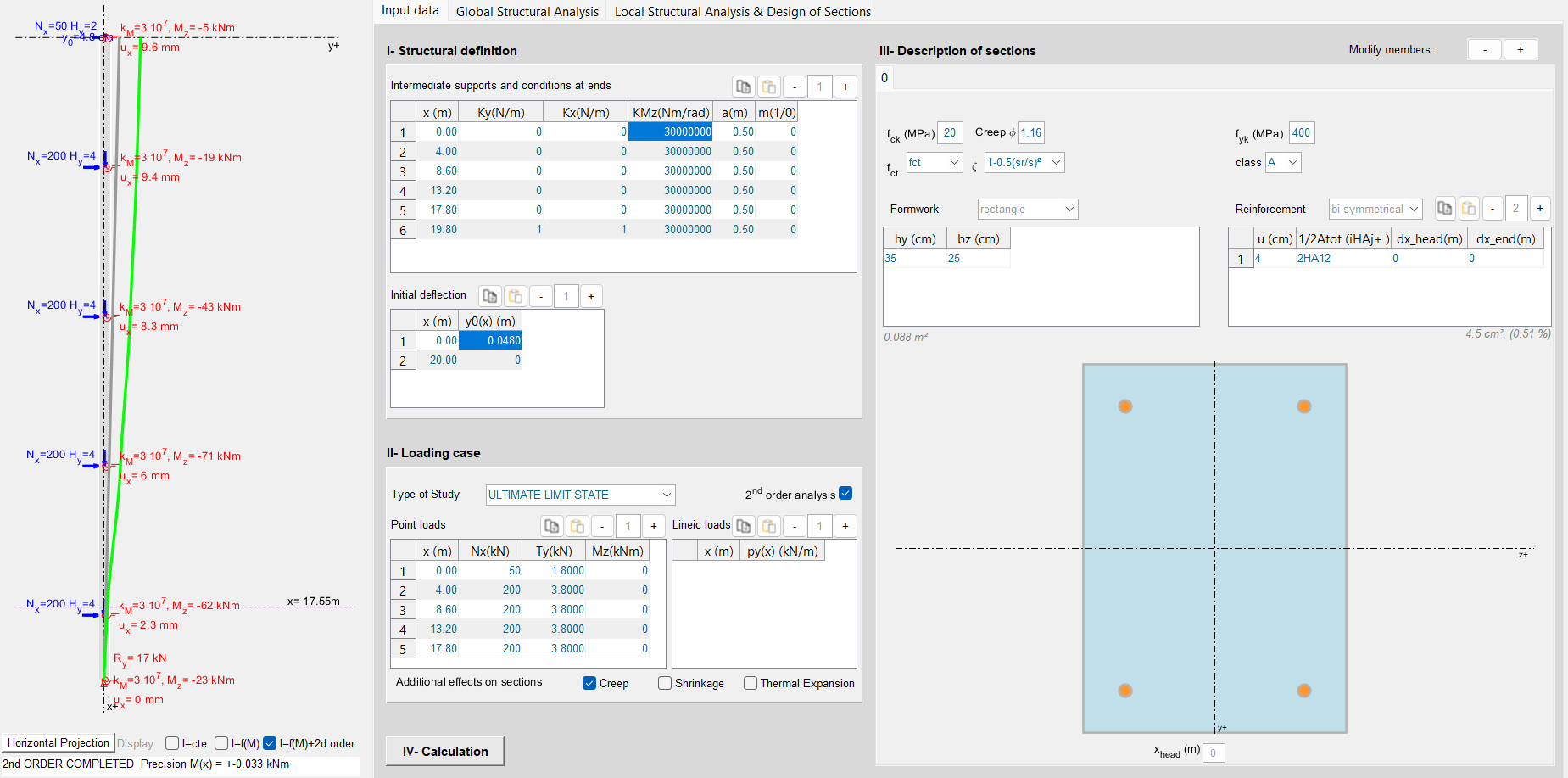
Calculation setup
All the data of the problem are entered into the model and the calculation is launched:
Global structural analysis
The calculation converges to a stable solution and reveals the following structural analysis curves:
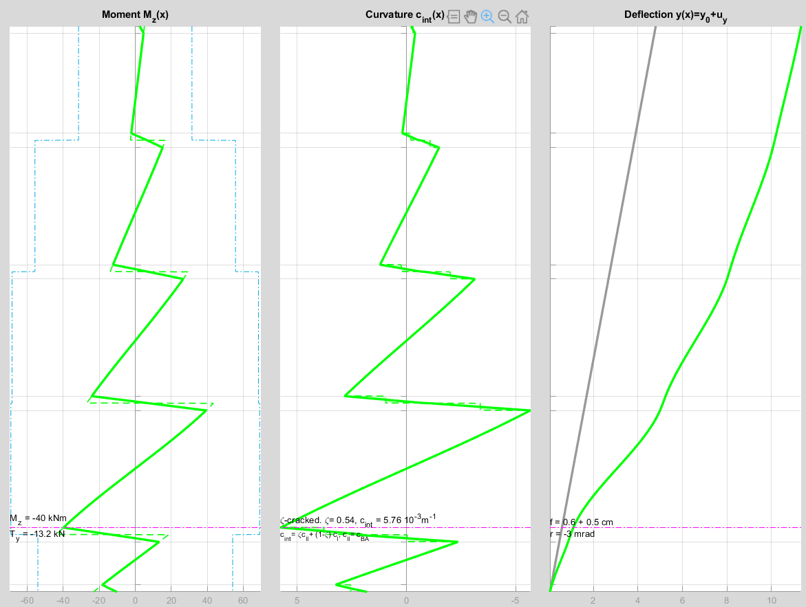
- in terms of deformation, the initial “construction deflection” of 4,8 cm at the top is found, to which a ULS deformation of 6.5 cm, including second-order effects, is added, giving a total value of 11.3 cm;
- the moment and curvature exhibit discontinuities whose amplitude corresponds to the moment transferred through each beam;
- at the node, the dotted curve represents the moment value between axes, while the bold line represents the capped moment value;
- the axial force increases along the height, progressively increasing the flexural resistance limit of the column sections (blue dotted curve) up to x = 17.8 m;
- the most highly stressed section, i.e. the section where the demand approaches the resistance most closely, is located at x = 17.55 m.
Second-order effects
The superposition of the final curves (in green) with the curves without second-order effects (in blue) highlights the impact of second-order effects.
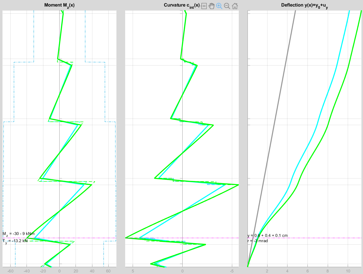
At the location of the most highly stressed section, second-order effects increase the moment by 9/30 = 30%.
Local analysis of the most highly stressed section
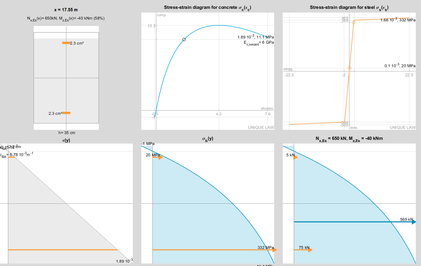
At the most highly stressed section, the extreme concrete fibre enters tension while remaining uncracked.
NB: the model indeed makes use of the favourable effect of tensioned concrete participation in accordance with EC2 §5.8.6 (5).
The stress in the concrete reaches a significant value of 11,1 MPa, > 0.5 fck. Consequently, the secant modulus of the concrete is reduced to approximately 50% of the original elastic modulus (which was equal to Ecd / γCE / (1 + ϕef)).
It may also be noted that the contribution of the reinforcement is essentially a compressive contribution, amounting to 13% of the axial force.
These last two observations highlight the difficulty of representing such a use case within a conventional elastic analysis model: the contribution of reinforcement and the continuous evolution of the concrete secant modulus along the column complicate the determination of an equivalent modulus and inertia that would provide “accurate” deformations from a regulatory standpoint in a global stability analysis.
Conclusion of the example
The detailed global stability study of this structure shows that the structure is stable: the multi-storey frame system is capable of resisting wind effects and possible building out-of-plumb conditions, even in the absence of bracing walls.
This conclusion validates the original designer’s approach, whether the use of these frames was a deliberate choice to deal with wind effects, or whether stability was implicitly assumed not to require verification.
Good practice rules in reinforced concrete design nevertheless generally recommend at least three non-concurrent shear walls in buildings, in order to stabilise structures under horizontal loads and avoid any a priori complex study of global and second-order stability (see also the section “ principles of bracing ” on this topic). EC2 §5.8.3.3 moreover provides a simple rule allowing easy validation of such an approach.
The example presented here highlights possible alternatives and different design strategies that may find particular relevance in contemporary projects.
Provided that their design is properly controlled, reinforced concrete structures braced by multi-storey frames indeed offer several advantages:
- a reduced carbon footprint by limiting concrete to the structural frame only, eliminating the use of “default” shear walls for bracing purposes and making full use of column–beam systems not only for gravity loads but also for bracing;
- increased modularity in designs intended for evolving uses, or more generally where bracing systems are functionally constraining;
- overall building flexibility promoting ductile seismic behaviour, thereby limiting seismic forces transmitted to the foundations;
- reduction of thermal expansion and shrinkage effects, as the presence of walls creates significant stiffness, potentially leading to higher tensile forces in horizontal elements.